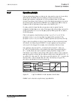


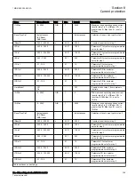


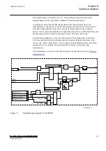


In a comparator, the DFT or RMS values are compared to the set operation current
value of the function (
I1>
,
I2>
,
I3>
or
I4>
) for each phase current. If a phase
current is larger than the set operation current, outputs START, STx, STL1, STL2
and STL3 are activated without delay. Output signals STL1, STL2 and STL3 are
common for all steps. This means that the lowest set step will initiate the
activation. The START signal is common for all three phases and all steps. It shall
be noted that the selection of measured value (DFT or RMS) do not influence the
operation of directional part of OC4PTOC.
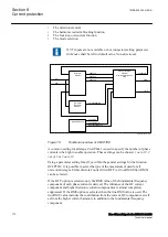
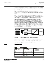
Service values for individually measured phase currents are available on the local
HMI for OC4PTOC function, which simplifies testing, commissioning and in
service operational checking of the function.
A harmonic restrain of the function can be chosen. A set 2nd harmonic current in
relation to the fundamental current is used.
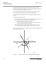
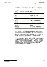
The function can be directional.The direction of a fault is given as the current angle
in relation to the voltage angle. The fault current and fault voltage for the
directional function are dependent on the fault type. The selection of the measured
value (DFT or RMS) does not influence the operation of the directional part of
OC4PTOC. To enable directional measurement at close-in faults, causing a low
measured voltage, the polarization voltage is a combination of the apparent voltage
(85%) and a memory voltage (15%). The following combinations are used.
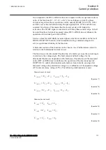
Phase-phase short circuit:
1 2
1
2
1 2
1
2
=
-
=
-
refL L
L
L
dirL L
L
L
U
U
U
I
I
I
EQUATION1449 V1 EN-US
(Equation 17)
2 3
2
3
2 3
2
3
=
-
=
-
refL L
L
L
dirL L
L
L
U
U
U
I
I
I
EQUATION1450 V1 EN-US
(Equation 18)
3 1
3
1
3 1
3
1
=
-
=
-
refL L
L
L
dirL L
L
L
U
U
U
I
I
I
EQUATION1451 V1 EN-US
(Equation 19)
Phase-earth short circuit:
1
1
1
1
=
=
refL
L
dirL
L
U
U
I
I
EQUATION1452 V1 EN-US
(Equation 20)
2
2
2
2
=
=
refL
L
dirL
L
U
U
I
I
EQUATION1453 V1 EN-US
(Equation 21)
3
3
3
3
=
=
refL
L
dirL
L
U
U
I
I
EQUATION1454 V1 EN-US
(Equation 22)
1MRK 505 394-UEN A
Section 8
Current protection
Line differential protection RED650 2.2 IEC
173
Technical manual
Summary of Contents for RED650
Page 1: ...RELION 650 SERIES Line differential protection RED650 Version 2 2 Technical manual...
Page 2: ......
Page 36: ...30...
Page 46: ...40...
Page 232: ...226...
Page 272: ...266...
Page 288: ...282...
Page 306: ...300...
Page 406: ...400...
Page 436: ...430...
Page 502: ...496...
Page 614: ...608...
Page 628: ...622...
Page 644: ...638...
Page 760: ...754...
Page 778: ...772...
Page 814: ...808...
Page 870: ...864...
Page 874: ...868...
Page 924: ...918...
Page 925: ...919...