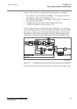


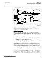


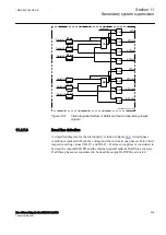


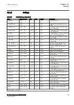


DeltaIL1
DeltaUL1
DeltaIL2
DeltaUL2
DeltaIL3
DeltaUL3
STDIL1
STDIL2
STDIL3
STDI
STDU
STDUL1
STDUL2
STDUL3
IEC12000165-1-en.vsd
intBlock
OR
OR
20 ms
20 ms
OR
t
20 ms
t
20 ms
t
20 ms
AND
AND
AND
AND
AND
AND
AND
AND
t
20 ms
t
20 ms
t
20 ms
t
20 ms
t
t
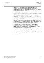
IEC12000165 V1 EN-US
Figure 139:
Internal signals DeltaU or DeltaI and the corresponding output
signals
11.2.7.3
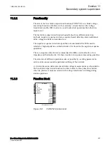
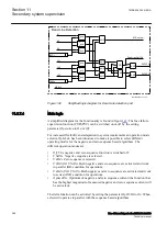
Dead line detection
M13679-44 v4
A simplified diagram for the functionality is found in figure
condition is indicated if both the voltage and the current in one phase is below their
respective setting values
UDLD<
and
IDLD<
. If at least one phase is considered to
be dead the output DLD1PH and the internal signal DeadLineDet1Ph is activated.
If all three phases are considered to be dead the output DLD3PH is activated
1MRK 505 394-UEN A
Section 11
Secondary system supervision
Line differential protection RED650 2.2 IEC
295
Technical manual
Summary of Contents for RED650
Page 1: ...RELION 650 SERIES Line differential protection RED650 Version 2 2 Technical manual...
Page 2: ......
Page 36: ...30...
Page 46: ...40...
Page 232: ...226...
Page 272: ...266...
Page 288: ...282...
Page 306: ...300...
Page 406: ...400...
Page 436: ...430...
Page 502: ...496...
Page 614: ...608...
Page 628: ...622...
Page 644: ...638...
Page 760: ...754...
Page 778: ...772...
Page 814: ...808...
Page 870: ...864...
Page 874: ...868...
Page 924: ...918...
Page 925: ...919...