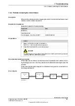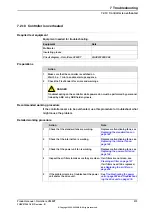
LEDs on the main computer:
xx2100001068
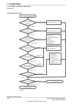
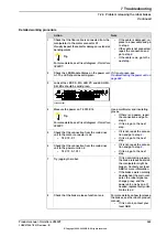
Detailed working procedure
Note
Action
LED Module status should be
green.
•
If not, see
•
If the power unit is ok, check
that incoming mains is well
connected and that the in-
coming mains switch is
turned on.
Check
Module status
LED on power unit A1.
1
LED PS should be green.
•
If not, see
•
If the power unit is ok, check
that the power inlet is prop-
erly connected and the
power inlet switch is turned
on.
For more details about the LEDs,
see
Troubleshooting the robot sig-
nal exchange proxy on page 405
Look at the LED PS.
2
LED MS should be green.
•
If not, see
the robot signal exchange
proxy on page 405
.
Look at the LED MS.
3
LED PC and LED HMI should be
green.
•
If not, see
the robot signal exchange
proxy on page 405
Look at the LEDs PC and HMI.
4
For more details about the LEDs,
see
.
Look at the LEDs PC PWR, PC HDD, and PC
STAT.
5
If the drive unit status LED is not
lit, see
.
Check the drive unit status LED.
6
If the problem remains, contact ABB.
7
Tip
For more details, see
Circuit diagram - OmniCore V250XT
.
Product manual - OmniCore V250XT
359
3HAC073447-001 Revision: B
© Copyright 2020-2022 ABB. All rights reserved.
7 Troubleshooting
7.2.2 Start-up failure
Continued
Summary of Contents for OmniCore V250XT
Page 1: ...ROBOTICS Product manual OmniCore V250XT ...
Page 34: ...This page is intentionally left blank ...
Page 50: ...This page is intentionally left blank ...
Page 174: ...This page is intentionally left blank ...
Page 410: ...This page is intentionally left blank ...
Page 418: ...This page is intentionally left blank ...
Page 454: ......
Page 455: ......


