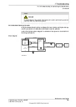
Look at the following block diagram to understand how power is connected from
incoming and forward.
Block diagram
AC
input
L1, L2, L3
Mains
connection
X0
Mains
switch
Q0
Power
unit
A1
X1
X6
PE1, PE2
L
1
,
L
2
,
L
3
Fuse
F1
L
1
,
L
2
,
L
3
L
1
,
L
2
,
L
3
Power
supply
ODVA
T6, 79
X1
Process
power
supply
T5, T8
X1
2
4
V
T
R
U
N
K
X1
X2
X3
PC
PS
X4
X13
HMI
24V SYS DRV
LED
MS
LED
Main
computer
A2
24V PC
LED
X1
24V HMI
LED
HMI
connection
X4
FlexPendant
24V HMI
X9
Robot
signal
exchange
proxy
K2
X7/X15
AC
LED
Safety
board
K3
X1
24V SYS
xx2100001063
Continues on next page
Product manual - OmniCore V250XT
353
3HAC073447-001 Revision: B
© Copyright 2020-2022 ABB. All rights reserved.
7 Troubleshooting
7.2.1 No LEDs are lit on the controller
Continued
Summary of Contents for OmniCore V250XT
Page 1: ...ROBOTICS Product manual OmniCore V250XT ...
Page 34: ...This page is intentionally left blank ...
Page 50: ...This page is intentionally left blank ...
Page 174: ...This page is intentionally left blank ...
Page 410: ...This page is intentionally left blank ...
Page 418: ...This page is intentionally left blank ...
Page 454: ......
Page 455: ......


