


Required documents
Note
Article number
Document
3HAC074000-008
Circuit diagram - OmniCore
V250XT
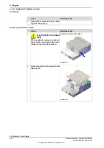
Removing the fieldbus master
Note
The fieldbus master is part of an assembly group, secured on a process plate.
To remove the fieldbus master, either lift out the assembly group and then remove
the fieldbus master, or take out the parts on top of the main computer and then
remove the fieldbus master.
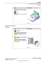
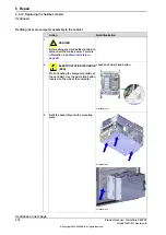
Preparations
Note/Illustration
Action
DANGER
Before doing any work inside the cabinet,
disconnect the mains power. For more
information, see
1
.
Open the door.
2
Location of wrist strap button:
ELECTROSTATIC DISCHARGE
(ESD)
The unit is sensitive to ESD. Before
handling the unit read the safety inform-
ation in section
3
xx2100000318
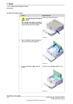
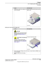
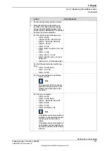
Removing the main computer assembly
Note/Illustration
Action
Disconnect all the connectors on the as-
sembly group of the robot signal ex-
change proxy, Ethernet switch (option),
connected services gateway, and main
computer.
1
Continues on next page
Product manual - OmniCore V250XT
269
3HAC073447-001 Revision: B
© Copyright 2020-2022 ABB. All rights reserved.
5 Repair
5.2.12 Replacing the fieldbus master
Continued
Summary of Contents for OmniCore V250XT
Page 1: ...ROBOTICS Product manual OmniCore V250XT ...
Page 34: ...This page is intentionally left blank ...
Page 50: ...This page is intentionally left blank ...
Page 174: ...This page is intentionally left blank ...
Page 410: ...This page is intentionally left blank ...
Page 418: ...This page is intentionally left blank ...
Page 454: ......
Page 455: ......


