


Note/Illustration
Action
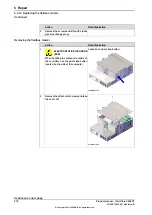
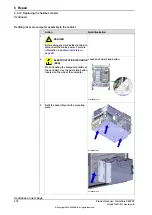
Fasten the assembly with the screws.
4
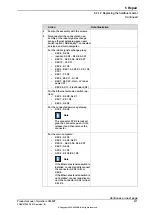
Reconnect all the connectors on as-
sembly of the robot signal exchange
proxy, ethernet extension-seven port
switch (option), ABB ability™ connected
services, and main computer.
5
For the robot signal exchange proxy:
•
K2.X8 - A2.X6
•
(option): K2.X2 - K4.X8, A2.X1
•
K2.X12 - A2.K3.X6, A2.K3.X7
•
K2.X10 - A1.X13
•
K2.X4 - A1.X9
•
K2.X3 - K6.X1, A2.K3.X1, K5.1.X4,
K7.X1
•
K2.X1 - T2.X2
•
K2.X6, K2.X11 - A1.X2
•
K2.X7, K2.X22 - Harn. LV robot
power (X1)
•
K2.X9 & X13 - FlexPendant (X4)
For the Ethernet extension switch (op-
tion):
•
K2.X2 - K4.X8, A2.X1
•
K4.X7 - K5.1.X5
•
K4.X6 - A2.X4
For the connected services gateway:
•
K7.X2 - A2.X5
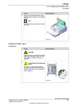
Note
The connector K7.X2 is locked;
grab the connector, push it in to
release it and then remove the
connector.
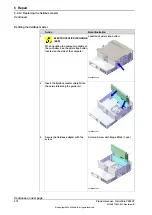
For the main computer:
•
K2.X8 - A2.X6
•
K2.X2 - K4.X8, A2.X1
•
K2.X12 - A2.K3.X6, A2.K3.X7
•
K6.X2 - A2.X9
•
A2.X5 - K7.X2
•
A2.X4 - K4.X6/K5.1.X5
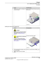
Note
If the Ethernet extension switch is
installed, connect and disconnect
the connector A2.X4 to/from
K4.X6.
If the Ethernet extension switch is
not installed, connect and discon-
nect the connector A2.X4 to/from
K5.1.X5.
Continues on next page
Product manual - OmniCore V250XT
277
3HAC073447-001 Revision: B
© Copyright 2020-2022 ABB. All rights reserved.
5 Repair
5.2.12 Replacing the fieldbus master
Continued
Summary of Contents for OmniCore V250XT
Page 1: ...ROBOTICS Product manual OmniCore V250XT ...
Page 34: ...This page is intentionally left blank ...
Page 50: ...This page is intentionally left blank ...
Page 174: ...This page is intentionally left blank ...
Page 410: ...This page is intentionally left blank ...
Page 418: ...This page is intentionally left blank ...
Page 454: ......
Page 455: ......


