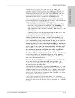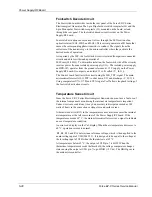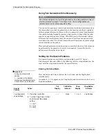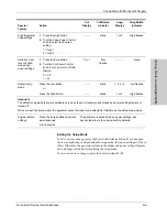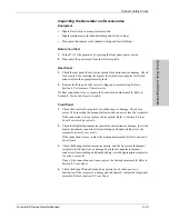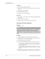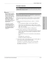
Connections for Monopolar Surgery
Setup, T
e
st
s, and Adjustment
s
Force EZ-C Series Service Manual
6-11
Important
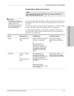
Activating the Surgical Instrument
To activate an instrument in
the blend mode, press the Cut
(yellow) button on the
handswitching instrument, or
press the Cut pedal on the
monopolar footswitch.
To activate a handswitching instrument, use the controls on the instrument or on
the appropriate footswitch. To activate a footswitching instrument, you must use a
footswitch.
To reduce the possibility of alternate site burns that may be caused by RF leakage
currents, avoid unnecessary and prolonged activation of the generator.
If you use bipolar output when a return electrode is applied to the patient, the
generator automatically deactivates the return electrode circuit to eliminate the
possibility of current dispersal.
Notice
Do not activate the generator until the forceps have made contact with the
patient. Product damage may occur.
Mode
Handswitching
Footswitching
Activation Indicator
Bipolar
Close forceps tines
firmly
Bipolar footswitch connected to
rear panel – press pedal
or
Monopolar footswitch
connected to front panel –
verify that the left arrow at the
Footswitch Selector button
illuminates and press either
pedal
Activation tone sounds –
Bipolar indicator illuminates
blue
Monopolar
Press Cut or Coag
button
or
Close forceps tines
firmly
Monopolar footswitch
connected to front panel –
verify that the right arrow at the
Footswitch Selector button
illuminates and press the cut or
coag pedal
or
Monopolar footswitch
connected to rear panel – press
cut or coag pedal
Activation tone sounds – Cut
indicator illuminates yellow or
Coag indicator illuminates blue
Содержание Force EZ - C Series
Страница 1: ...Service Manual Valleylab Force EZ C Series Electrosurgical Generator with Instant Response Technology...
Страница 6: ...vi Force EZ C Series Service Manual...
Страница 20: ...1 6 Force EZ C Service Manual...
Страница 64: ...4 30 Force EZ C Series Service Manual...
Страница 156: ...7 26 Force EZ C Series Service Manual...
Страница 158: ...Interconnect Diagram 8 2 Force EZ C Series Service Manual Interconnect Diagram Figure 8 1 Electric cable connections...
Страница 208: ...10 18 Force EZ C Series Service Manual...


