Generator Assembly Parts List
10-6
Force EZ-C Series Service Manual
6
Assembly, left front heat sink
Includes
...
Heat sink, 5.29 wide
Diode, 8 A, 600 V (4)
Resistor, MF 150
Ω
± 5%, 20 W
Screw, panhd M2.5 x 10 mm (5)
Washer, shoulder (5)
207 000 211
239 850 034
234 400 251
237 050 159
213 400 057
7
Assembly, Control Board
Refer to
Control Board Components
in this
section.
201 500 023
8
Low voltage power supply
207 000 185
9
Cable assembly, low voltage power supply
input
207 500 531
10
Cable assembly, power 4 wire
207 500 532
11
Assembly, Footswitch board
Refer to
Footswitch Board Components
in
this section.
201 342 002
12
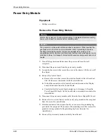
Assembly, power entry module
Includes
...
Line filter, 10A
Cable assembly, power entry
Ground wire assembly
Fuse, T4A, 5 x 20 mm, 220 V (2)
Fuse, F8A, 5 x 20 mm, 120 V (2)
Tubing, heatshrink 81K 14 ID
202 701 974
251 400 007
207 500 533
207 500 535
215 100 074
215 100 070
249 001 002
17
Handle
223 300 054
21
Screw, panhd M4 x 8 mm (21)
237 050 113
26
Bracket, PCB support
223 100 993
Serial Port Plate
223 200 615
Item
Description
Part Number
Содержание Force EZ - C Series
Страница 1: ...Service Manual Valleylab Force EZ C Series Electrosurgical Generator with Instant Response Technology...
Страница 6: ...vi Force EZ C Series Service Manual...
Страница 20: ...1 6 Force EZ C Service Manual...
Страница 64: ...4 30 Force EZ C Series Service Manual...
Страница 156: ...7 26 Force EZ C Series Service Manual...
Страница 158: ...Interconnect Diagram 8 2 Force EZ C Series Service Manual Interconnect Diagram Figure 8 1 Electric cable connections...
Страница 208: ...10 18 Force EZ C Series Service Manual...


