Periodic Safety Check
Setup, T
e
st
s, and Adjustment
s
Force EZ-C Series Service Manual
6-19
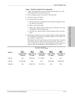
Step 2 – Check the output for the coag modes
1.
Connect the appropriate power resistor (refer to the table below) across the
output receptacles at the end of the test cables.
2.
Press the appropriate mode button (refer to the table below).
3.
Set the coag power to 120 watts.
4.
Test the monopolar coag output.
a.
Press the footswitch coag pedal and, while activating the generator, note
the output on the voltmeter.
b.
Release the footswitch pedal.
c.
Based on the voltmeter setting and the current transformer you are using,
calculate and record the output current.
d.
Verify that the generator output is within the range specified in the table
below.
5.
Repeat steps 1 through 4 for each coag mode setting and resistor combination.
For information on changing the low and high settings, refer to
Setting Up the
Special Features
in this section.
If the output is outside the specified range, calibrate the generator as described
in
Calibrating the Force EZ-C Series Electrosurgical Generator
in this
section. Then repeat this procedure. If the output for one or more coag modes
remains outside the specified range, call the Valleylab Service Center.
Generator Output (A
rms
)
Resistor
Low 1
Setting
(coag power @
120 watts)
Low 2
Setting
(coag power @
120 watts)
Low 3
Setting
(coag power @
120 watts)
High 1
Setting
(coag power @
120 watts)
High 2
Setting
(coag power @
120 watts)
200 ohm
N/A
0.714-0.831
0.714-0.831
N/A
N/A
500 ohm
0.452-0.525
N/A
N/A
0.452-0.525
0.452-0.525
2000 ohm
N/A
0.093-0.125
0.127-0.173
N/A
N/A
Содержание Force EZ - C Series
Страница 1: ...Service Manual Valleylab Force EZ C Series Electrosurgical Generator with Instant Response Technology...
Страница 6: ...vi Force EZ C Series Service Manual...
Страница 20: ...1 6 Force EZ C Service Manual...
Страница 64: ...4 30 Force EZ C Series Service Manual...
Страница 156: ...7 26 Force EZ C Series Service Manual...
Страница 158: ...Interconnect Diagram 8 2 Force EZ C Series Service Manual Interconnect Diagram Figure 8 1 Electric cable connections...
Страница 208: ...10 18 Force EZ C Series Service Manual...


