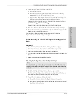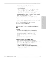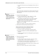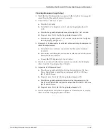
Calibrating the Force EZ-C Series Electrosurgical Generator
6-24
Force EZ-C Series Service Manual
Preparing for Calibration
You will need the following equipment to calibrate the Force EZ-C Series
Electrosurgical Generator:
•
Bipolar footswitch and monopolar footswitch
•
REM plug and resistor substitution box
•
Two small test cables (less than 24 inches long) with banana plugs
•
Current transformer (such as the Pearson Model 411 or equivalent)
•
True RMS voltmeter (such as the Fluke 8920A or equivalent)
•
Noninductive power resistors (such as a Dale NH-250) with these values (in
ohms): 10, 30, 50, 100, 200, 500, 750, 2000, and 3000.
If these exact values are not available, you may substitute series or parallel
combinations of other values.
•
X1000 high voltage scope probe (TEK P6015A or equivalent)
•
Oscilloscope (Tek 2445B or equivalent)
Entering Calibration Mode
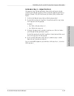
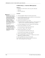
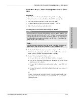
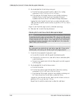
When you are in calibration mode, the calibration step number appears in the
Bipolar display. The value(s) associated with each calibration step appear in the
Cut and Coag displays. Use the Cut and Coag Power Control knobs to adjust the
displayed values.
1.
If the generator is off, turn it on.
If you removed and/or replaced the battery, alarm number 212 may appear in
the Cut display the first time you turn on the generator.
2.
To enter calibration mode, simultaneously press the Footswitch Selector,
Pure, and Desiccate buttons.
The first calibration step number (1) appears in the Bipolar display. For
instructions on completing this step, refer to
Calibration Step 1 – Verify the
Force EZ-C Series Electrosurgical Generator data
.
If an error occurs during calibration, an alarm number will appear in the Cut
display. Note the number and refer to Section 7,
Responding to System Alarms
for
the appropriate action to take.
Notice
After completing any calibration step, proceed to the next step to save the values
from the completed calibration step.
Содержание Force EZ - C Series
Страница 1: ...Service Manual Valleylab Force EZ C Series Electrosurgical Generator with Instant Response Technology...
Страница 6: ...vi Force EZ C Series Service Manual...
Страница 20: ...1 6 Force EZ C Service Manual...
Страница 64: ...4 30 Force EZ C Series Service Manual...
Страница 156: ...7 26 Force EZ C Series Service Manual...
Страница 158: ...Interconnect Diagram 8 2 Force EZ C Series Service Manual Interconnect Diagram Figure 8 1 Electric cable connections...
Страница 208: ...10 18 Force EZ C Series Service Manual...


