Correcting Malfunctions
T
roubleshooting
Force EZ-C Series Service Manual
7-5
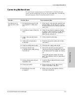
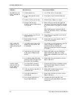
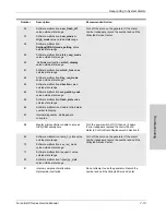
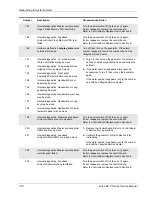
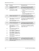
Blank or confusing
LED display
1.
Faulty ribbon cable between
Control board and Display board
1.
Check/connect ribbon cable that connects the
Display board to the Control board.
2.
Incorrect display modes communi-
cated through the Control board
2.
Replace the Control board. Refer to
Control
Board
in Section 8.
3.
Display board malfunction
3.
Replace the Display board. Refer to
Display
Board
in Section 8.
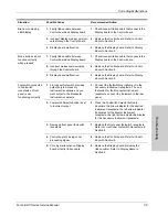
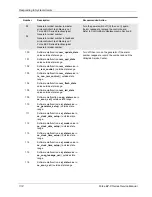
Mode buttons do not
function correctly
when pressed
1.
Faulty ribbon cable between
Control board and Display board
1.
Check/connect ribbon cable that connects the
Display board to the Control board.
2.
Incorrect modes communicated
through the Control board
2.
Replace the Control board. Refer to
Control
Board
in Section 8.
3.
Display board malfunction
3.
Replace the Display board. Refer to
Display
Board
in Section 8.
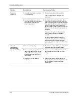
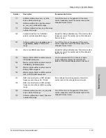
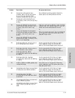
Footswitch connected
to Footswitch
receptacle on front
panel is not
functioning correctly
1.
Front panel footswitch provides
output only to Accessory
Instrument receptacle and you
want output to the Monopolar
Instrument receptacle
1.
Connect the footswitching instrument to the
Accessory Instrument receptacle. To use a
footswitch for the Monopolar Instrument
receptacle, connect the footswitch to the rear
panel.
2.
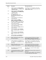
Footswitch Selector button is set
to incorrect output
2.
Press the Footswitch Selector button to
illuminate the arrow indicator for the desired
instrument receptacle: the left arrow indicator
illuminates for the Bipolar Instrument
receptacle; the right arrow indicator illuminates
for the Accessory Instrument receptacle.
3.
Damaged front panel footswitch
receptacle
3.
Replace the front panel footswitch receptacle.
Refer to
Front Panel Footswitch Receptacle
in
Section 8.
4.
Control board is losing or not
processing signal
4.
Replace the Control board. Refer to
Control
Board
in Section 8.
5.
Circuitry malfunction on Display
board or faulty ribbon cable
5.
Replace the Display board (including the
ribbon cable). Refer to
Display Board
in
Section 8.
Situation
Possible Cause
Recommended Action
Содержание Force EZ - C Series
Страница 1: ...Service Manual Valleylab Force EZ C Series Electrosurgical Generator with Instant Response Technology...
Страница 6: ...vi Force EZ C Series Service Manual...
Страница 20: ...1 6 Force EZ C Service Manual...
Страница 64: ...4 30 Force EZ C Series Service Manual...
Страница 156: ...7 26 Force EZ C Series Service Manual...
Страница 158: ...Interconnect Diagram 8 2 Force EZ C Series Service Manual Interconnect Diagram Figure 8 1 Electric cable connections...
Страница 208: ...10 18 Force EZ C Series Service Manual...

