Power Supply/RF Board
8-30
Force EZ-C Series Service Manual
7.
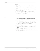
Install the front panel assembly.
a.
Position the front panel assembly in front of the chassis and carefully slide
it into the electrical contacts on the Power Supply/RF board.
b.
Install the four screws that secure the front panel to the chassis.
c.
Connect the power switch cable to J14 on the Power Supply/RF board.
d.
Connect the Display board ribbon cable to the Control board and lock the
connector.
8.
Position the cover above the chassis and slide it down. Tighten the four
screws that secure the cover to the chassis.
Содержание Force EZ - C Series
Страница 1: ...Service Manual Valleylab Force EZ C Series Electrosurgical Generator with Instant Response Technology...
Страница 6: ...vi Force EZ C Series Service Manual...
Страница 20: ...1 6 Force EZ C Service Manual...
Страница 64: ...4 30 Force EZ C Series Service Manual...
Страница 156: ...7 26 Force EZ C Series Service Manual...
Страница 158: ...Interconnect Diagram 8 2 Force EZ C Series Service Manual Interconnect Diagram Figure 8 1 Electric cable connections...
Страница 208: ...10 18 Force EZ C Series Service Manual...

