Front Panel Power Switch
8-12
Force EZ-C Series Service Manual
Front Panel Power Switch
1.
Remove the front panel assembly (observe all warnings and cautions). Refer
to
Front Panel
earlier in this section.
2.
Inside the front panel, use the pliers to press the four tabs that secure the
power switch and push the switch (and connected cable) out the opening.
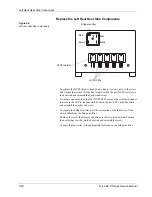
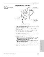
Figure 8-2.
Power switch and cable
connections
1.
Check and correct the cable connections on the new power switch assembly,
using the illustration and the assembly you just removed as a reference.
2.
Outside the front panel, route the power switch cable through the power
switch opening.
3.
Position the power switch with the on ( | ) switch above the off ( O ) switch.
Press to snap the switch into place.
4.
Reinstall the front panel assembly. Refer to
Front Panel
earlier in this section.
Tab
Blue
Brown
Содержание Force EZ - C Series
Страница 1: ...Service Manual Valleylab Force EZ C Series Electrosurgical Generator with Instant Response Technology...
Страница 6: ...vi Force EZ C Series Service Manual...
Страница 20: ...1 6 Force EZ C Service Manual...
Страница 64: ...4 30 Force EZ C Series Service Manual...
Страница 156: ...7 26 Force EZ C Series Service Manual...
Страница 158: ...Interconnect Diagram 8 2 Force EZ C Series Service Manual Interconnect Diagram Figure 8 1 Electric cable connections...
Страница 208: ...10 18 Force EZ C Series Service Manual...


