Handle
8-16
Force EZ-C Series Service Manual
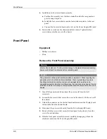
Procedure
1.
Turn off the generator and disconnect the power cord from the wall
receptacle.
2.
Loosen the four screws that secure the cover to the chassis. Lift the cover off
the chassis.
3.
Locate the fuse at the rear/center of the Power Supply/RF board. Use a fuse
puller to remove the blown fuse.
4.
Replace the blown fuse with one of the same type and rating (F6.3A).
5.
Position the cover above the chassis and slide it down. Tighten the four
screws that secure the cover to the chassis.
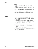
Handle
1.
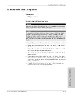
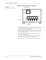
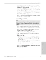
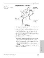
Remove the Power Supply/RF board and attached heat sinks (observe all
warnings and cautions). Refer to
Power Supply/RF board
later in this section.
2.
Remove the handle.
a.
Tilt the generator onto its side to access the underside of the chassis.
b.
Remove the four screws that secure the handle to the floor of the chassis.
c.
Note the orientation of the handle, then remove the handle.
3.
Install a new handle.
a.
Position the new handle inside the chassis. Hold it in place and install the
four screws on the underside of the chassis that secure the handle to the
chassis.
b.
Return the generator to an upright position.
4.
Reinstall the Power Supply/RF board and attached heat sinks. Refer to
Power
Supply/RF board
later in this section.
Содержание Force EZ - C Series
Страница 1: ...Service Manual Valleylab Force EZ C Series Electrosurgical Generator with Instant Response Technology...
Страница 6: ...vi Force EZ C Series Service Manual...
Страница 20: ...1 6 Force EZ C Service Manual...
Страница 64: ...4 30 Force EZ C Series Service Manual...
Страница 156: ...7 26 Force EZ C Series Service Manual...
Страница 158: ...Interconnect Diagram 8 2 Force EZ C Series Service Manual Interconnect Diagram Figure 8 1 Electric cable connections...
Страница 208: ...10 18 Force EZ C Series Service Manual...


