Periodic Safety Check
Setup, T
e
st
s, and Adjustment
s
Force EZ-C Series Service Manual
6-15
Important
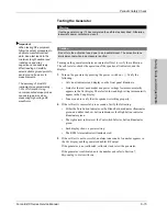
Testing the Generator
When testing RF equipment,
follow these test procedures to
duplicate manufacturer test
data. Keep test leads to the
minimum length usable; lead
inductance and stray
capacitance can adversely
affect readings. Carefully
select suitable ground points to
avoid ground loop error in
measurements.
The accuracy of most RF
instruments is approximately
1-5% of full scale. Using
uncompensated scope probes
causes large errors when
measuring high voltage RF
waveforms.
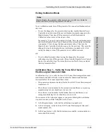
Turning on the generator initiates an internal self-test to verify the calibration.
The self-test also checks the operation of the speaker, all indicators, and the
displays.
1.
Turn on the generator by pressing the power switch on ( | ). Verify the
following:
•
All visual indicators and displays on the front panel illuminate.
•
Status for the last used modes and power settings feature momentarily
appears in the Cut display. The selected low and high settings momentarily
appear in the Coag display.
•
Tones sound to verify that the speaker is working properly.
2.
If the self-test is successful, a tone sounds. Verify the following:
•
Either the Pure button indicator or the Blend button indicator illuminates
green, and either the Low button indicator or the High button indicator
illuminates green.
•
The right arrow indicator at the Footswitch Selector button illuminates
green.
•
Each display shows a power setting.
•
The REM Alarm indicator illuminates red.
3.
If the self-test is not successful, an alarm tone sounds. A number appears in
the Cut display and the generator disables RF output.
If the generator is not calibrated, calibrate it and retest the generator.
If the generator is calibrated, note the number and refer to Section 7,
Responding to System Alarms
.
Warning
Use the generator only if it has completed the self-test as described. Otherwise,
inaccurate power outputs may result.
Caution
Do not turn the activation tone down to an inaudible level. The activation tone
alerts personnel when an accessory is active.
Содержание Force EZ - C Series
Страница 1: ...Service Manual Valleylab Force EZ C Series Electrosurgical Generator with Instant Response Technology...
Страница 6: ...vi Force EZ C Series Service Manual...
Страница 20: ...1 6 Force EZ C Service Manual...
Страница 64: ...4 30 Force EZ C Series Service Manual...
Страница 156: ...7 26 Force EZ C Series Service Manual...
Страница 158: ...Interconnect Diagram 8 2 Force EZ C Series Service Manual Interconnect Diagram Figure 8 1 Electric cable connections...
Страница 208: ...10 18 Force EZ C Series Service Manual...


