ADVANCED SYSTEM OPERATION
Section 9-15
NONE
This selection turns off Vector Optimizer.
Vector Scaling
This feature allows you to calibrate vector cutting or vector engraving to your particular
application. To calibrate the system, as an example, draw a precise, 5” x 5” square in your
graphics software. In the printer driver, set the laser power and speed setting to vector mark (do
not cut through) this square onto some scrap material. After marking, remove the material and
with a precision measuring device such as a caliper, measure the square in both the horizontal
(X) and vertical (Y) directions. Let’s say that the measurement was 4.997”x and 4.996”y. Use the
formula (desired length/measured length) and enter the result into the X-axis and Y-axis boxes
respectively. In this example, the result would be X-axis = 1.0006 to 1.0000 and Y-axis = 1.0008
to 1.0000. The printer driver will scale the images larger for numbers greater than 1.0000 and will
scale the image smaller for numbers less than 1.0000. After changing the numbers, repeat the
marking procedure and verify that the square is scaled correctly. We used a 5” by 5” square just
as an example but you can use any size object that is smaller than the maximum size of the
engraving field. Using the Vector scaling feature with larger images produces more accurate
results. Keep in mind that this feature
DOES NOT
scale raster images so if you combine raster
and vector images in one file, the raster image may not align with your vectors. You will need to
manually position your raster images in their desired position.
Do not attempt to use the vector-scaling feature when your graphic
extends out to the absolute edge of the engraving field. You may
accidentally cause the driver to attempt to print past the edge of the
maximum allowable page size. Unexpected results may occur. If you
use this feature, the actual allowable page size decreases by the
same amount that you are attempting to offset.
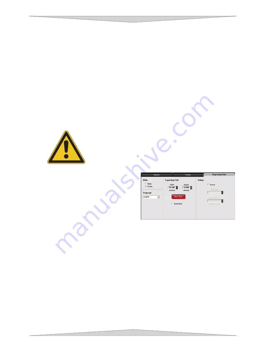
Engraving Field Sub-Tab
Units
This allows you to change between Metric and
Inches.
Language
Select from many different languages in this
drop down list. Some language changes will
not take effect until the printer control panel is closed and then re-opened.
Engraving Field
Width and Height
The page size that you enter here
MUST
match the page size in your graphics software
program
EXACTLY
and it is up to the operator to enter in the correct settings. Select the
metric box if metric units are desired.
NOTE:
Incorrect use of this feature may cause no graphics, partial graphics, erroneous
graphics, or a misaligned graphics output, relative to the application material, to occur. To
avoid problems, we recommend that set it to the maximum field size of your laser system
(click the Max Size button) and also set your graphics software programs page size to match.
Max Size Button
Clicking on this button restores the driver back to the default maximum page size that your
model can accept.
Dual Head
Dual Head is also an optional accessory. If you have purchased this option, please refer to
the ACCESSORIES section of the manual for more information.
Содержание PLS3.60
Страница 8: ......
Страница 20: ...SAFETY Section 1 12 ...
Страница 21: ...Part 1 Initial Setup ...
Страница 22: ......
Страница 30: ...INSTALLATION Section 2 10 ...
Страница 44: ...GRAPHICS SOFTWARE SETUP Section 3 14 ...
Страница 58: ...MAKING A SAMPLE Section 5 4 ...
Страница 59: ...Part 2 Laser System Essentials ...
Страница 60: ......
Страница 70: ...BASIC SYSTEM FEATURES Section 6 12 ...
Страница 76: ...BASIC MAINTENANCE Section 7 6 ...
Страница 77: ...Part 3 Accessories ...
Страница 78: ......
Страница 95: ...Part 4 Advanced User ...
Страница 96: ......
Страница 116: ...ADVANCED SYSTEM OPERATION Section 9 22 ...


