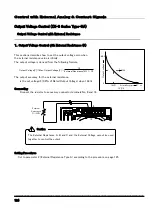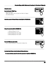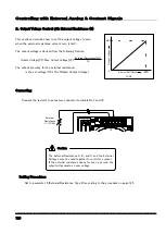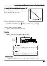
Using in Series/Parallel Operation
------------------------------------------------------------------------------------
116
2.Calibrating Slave Unit Output Settings
Calibrate the Slave unit to match the Slave’s output voltage with the Master’s voltage when in Series Operation.
Preparation
The following measuring device is required for calibration.
Voltage Measuring Digital Multimeter - 2 devices
No. of Display Digits: 5 1/2 or more Display Accuracy : 0.005% or more
※ (Equipped with a measuring range from 1mV~100V)
Offset/Full Scale Calibration of Slave Unit Output Voltage
1.
Detach the Load Wires and the Remote Sensing
Wires. Connect the Digital Multimeter to the output
terminal.
3. Press the PRESET key again and then the OUTPUT
key and set the output to ON.
Have the POWER switch turned ON and the output
turned OFF.
2.Press the PRESET key ① of the Master unit and
set to “0.01V” with the VOLTAGE dial ② and
“1.00A” with the CURRENT dial ③.
(See “Using as Constant Voltage Power Supply”
under “Basic Operations” on how to do this.)
4. Press the FUNC. key and turn the VOLTAGE dial to
display Settings Item 37 in the top Number Display.
5. Adjust the Slave unit's settings with the Current dial
to match the measured Master Unit's output voltage
displayed on the digital multimeter.
FUNC. lamp will light and the display in bottom Number Display
will disappear.
MEMO
CC
CV
OUTPUT POWER (%)
STEP
CURRENT
STEP
VOLTAGE
PRESET FUNC. REMOTE LOCK
20
60
100 LMT
40
80
OUTPUT
PRESET
OVP
OCP
FUNC.
ALARM RESET
OUTPUT
PRESET
OVP
OCP
FUNC.
ALARM RESET
①
②
+
-
V
+
-
V
スレーブ機
アナログコントロール
コネクタ
直列コントロール
コネクタ
マスター機
デジタルマル
チメータ
+
-
+
-
デジタルマル
チメータ
CC
CV
OUTPUT POWER (%)
STEP
CURRENT
STEP
VOLTAGE
PRESET FUNC. REMOTE LOCK
20
60
100 LMT
40
80
⇒Continued on next page
Analog Control
Connector
Series Control
Connector
Slave
Master
Digital
Multimeter
Digital
Multimeter
The ON/OFF of the "OUTPUT" is only valid with the Master
unit.
MEMO
OUTPUT
PRESET
OVP
OCP
POWER
FUNC.
LOCAL
LOCK
DISPLAY
A
B
C
STORE
MEMORY
CC
CV
OUTPUT POWER (%)
STEP
CURRENT
STEP
VOLTAGE
PRESET FUNC. REMOTE LOCK
ALARM RESET
20
60
100 LMT
40
80
ZX-S-400L
①
①
②
②
③
③
This feat
ure is not
applicable
to H t
ype.
Содержание ZX-S-H Series
Страница 1: ...Constant Voltage Constant Current DC Power Supply series Instruction Manual ...
Страница 37: ...Basic Operations 33 This is blank page ...
Страница 59: ...Useful Function 55 This is blank page ...
Страница 115: ...Using via Digital Data Communication 111 This is blank page ...
Страница 141: ...Controlling with External Analog Contact Signals 137 This is blank page ...
Страница 147: ...Special Loads 143 This is blank page 守 ...
Страница 188: ... 184 付録 External Diagrams ZX S 400H 400HA 4 M3 ...
Страница 189: ...Appendix 185 ZX S 800H 800HA ...
Страница 190: ...Appendix 186 ZX S 1600H 1600HA ...


