Using Objet Studio
5–36
DOC08010 Rev. A (DRAFT 1)
Grouping and
Ungrouping
Objects
You
ȱ
can
ȱ
manipulate
ȱ
two
ȱ
or
ȱ
more
ȱ
objects
ȱ
on
ȱ
the
ȱ
build
ȱ
tray,
ȱ
at
ȱ
the
ȱ
same
ȱ
time.
•
Selecting
ȱ
multiple
ȱ
objects
Manipulating
ȱ
done
ȱ
to
ȱ
one
ȱ
object
ȱ
affects
ȱ
all
ȱ
selected
ȱ
objects.
ȱ
For
ȱ
example,
ȱ
turning
ȱ
one
ȱ
object
ȱ
on
ȱ
its
ȱ
axis
ȱ
causes
ȱ
all
ȱ
selected
ȱ
objects
ȱ
to
ȱ
turn
ȱ
on
ȱ
their
ȱ
respective
ȱ
axes.
•
Converting
ȱ
the
ȱ
objects
ȱ
to
ȱ
an
ȱ
assembly
Separate
ȱ
objects
ȱ
become
ȱ
parts
ȱ
of
ȱ
one
ȱ
unit.
ȱ
For
ȱ
example,
ȱ
turning
ȱ
the
ȱ
assembly
ȱ
on
ȱ
its
ȱ
axis
ȱ
causes
ȱ
all
ȱ
its
ȱ
component
ȱ
parts
ȱ
to
ȱ
turn
ȱ
as
ȱ
one
ȱ
unit.
To convert objects to an assembly:
1. Select
ȱ
the
ȱ
objects
ȱ
(see
ȱ
“Selecting
ȱ
Objects”
ȱ
on
ȱ
page 18)
2. From
ȱ
the
ȱ
Object
ȱ
menu,
ȱ
select
ȱ
Group to Assembly
.
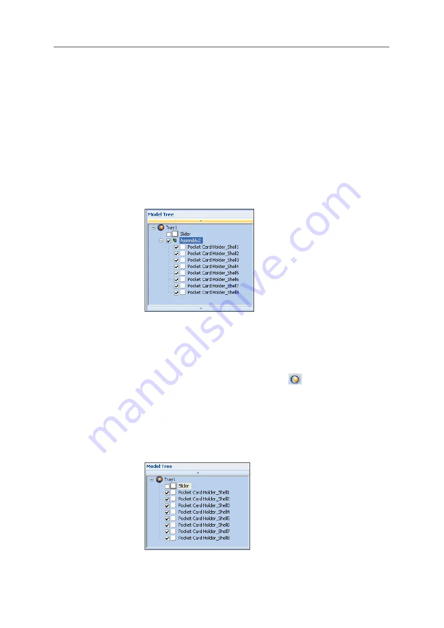
In
ȱ
the
ȱ
model
ȱ
tree,
ȱ
the
ȱ
objects
ȱ
now
ȱ
appear
ȱ
as
ȱ
children
ȱ
of
ȱ
a
ȱ
parent
ȱ
(assembly).
ȱ
Figure 5-46: Assembly in the model tree
After
ȱ
creating
ȱ
an
ȱ
assembly,
ȱ
you
ȱ
can
ȱ
save
ȱ
it
ȱ
as
ȱ
an
ȱ
objdf
ȱ
file,
ȱ
for
ȱ
re
Ȭ
use.
ȱ
(Saving
ȱ
the
ȱ
assembly
ȱ
is
ȱ
not
ȱ
necessary
ȱ
for
ȱ
manipulating
ȱ
and
ȱ
printing
ȱ
it.)
To save an assembly:
1. Select
ȱ
the
ȱ
assembly
ȱ
(either
ȱ
on
ȱ
the
ȱ
build
ȱ
tray
ȱ
or
ȱ
in
ȱ
the
ȱ
model
ȱ
tree).
2. From
ȱ
the
ȱ
Objet
ȱ
Studio
ȱ
Commands
ȱ
menu
ȱ
,
select
ȱ
Save As
.
3. In
ȱ
the
Save
ȱ
As
ȱ
dialog
ȱ
box,
ȱ
select
ȱ
the
ȱ
objdf
ȱ
format,
ȱ
choose
ȱ
a
ȱ
location,
ȱ
name
ȱ
the
ȱ
file,
ȱ
and
ȱ
click
ȱ
Save
.
To separate assemblies into individual objects (
stl
files):
1. Select
ȱ
the
ȱ
assembly
ȱ
(either
ȱ
on
ȱ
the
ȱ
build
ȱ
tray
ȱ
or
ȱ
in
ȱ
the
ȱ
model
ȱ
tree).
2. From
ȱ
the
ȱ
Object
ȱ
menu,
ȱ
select
ȱ
Ungroup
.
In
ȱ
the
ȱ
model
ȱ
tree,
ȱ
the
ȱ
elements
ȱ
are
ȱ
not
ȱ
parts
ȱ
of
ȱ
an
ȱ
assembly.
Figure 5-47: Separate objects in the model tree
Содержание P750K
Страница 1: ...User Guide English Stratasys P750K 3D Printer System...
Страница 2: ......
Страница 20: ...Safety 2 8 DOC08010 Rev A DRAFT 1...
Страница 30: ...Introducing the Stratasys P750K 3D Printing System 3 10 DOC08010 Rev A DRAFT 1...
Страница 196: ...Handling Printed Models 7 6 DOC08010 Rev A DRAFT 1...