background image

1-16

Chapter 1

Using the Basic System

Chapter 1

[AT]

PRESET

FOCUS

AUTO

FAR

END

A

D

B

E

C

F

EXIT

AT

P in P

TRACK

AUTO ZOOM

To recall a setting

Select a setting letter (A to F).
The camera is then adjusted to the setting stored under that letter.

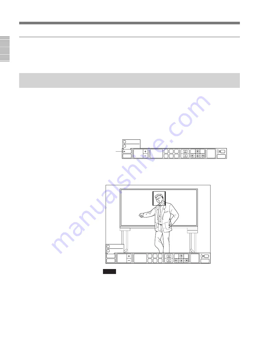
Tracking a Subject Automatically — AT (Automatic Target Tracking)
Function

You can have the camera memorize certain color and brightness so that
automatically tracks a subject having the memorized color and brightness.
If a subject almost goes out of the screen, the camera performs the pan/tilt
action so that the subject is placed in the middle of the screen.

1

Select [AT] from the CAMERA menu.
The AT sub-menu appears and the frame is displayed on the screen.

2

Select [

?

], [

>

], [

/

], [

.

] to perform the pan/tilt operation so that a

subject is placed into the frame.

Notes

• Be sure to place the subject so that the portion uniform in brightness

and color is in the frame.

• The camera might not recognize a subject if the portion different from

the subject in brightness and color, such as the backdrop, is placed
together in the frame.

PRESET

FOCUS

AUTO

FAR

END

A

D

B

E

C

F

EXIT

AT

P in P

TRACK

AUTO ZOOM

Basic Adjustments

Содержание PCS-5100

Страница 1: ... 1997 by Sony Corporation Operating Instructions Before operating the unit please read this manual thoroughly and retain it for future reference 3 859 843 17 1 Rollabout Package 5100 PCS 5100 PCS 5100P ...

Страница 2: ...ent is a label that contains among other information the FCC registration number for this equipment If requested this information must be provided to the telephone company 2 If this terminal equipment causes harm to the telephone network the telephone company will notify you in advance that temporary discontinuance of service may be required But if advance notice is not practical the telephone com...

Страница 3: ...or a Multi Meetings 1 20 Connecting With Other Parties 1 21 Changing the Picture Display Format 1 25 Ending the Multi Meeting 1 25 Connecting With MCU to Perform the Chairman Control 1 25 Quick operation For a quick understanding on the basic operation of the Rollabout Package read Chapter 1 Registering a Remote Party 2 1 Making an Entry 2 1 Modifying an Entry 2 8 Deleting an Entry 2 9 Setting the...

Страница 4: ...Transmitted Pictures 4 21 Displaying the Pointer on the Remote Party Screen 4 23 Printing Pictures Taken by a Document Scanner 4 24 Connecting a Printer 4 24 Selecting a Picture for Printing 4 24 Printing 4 25 Sending Video Images from a VCR 4 26 Connecting Video Equipment 4 26 Sending a Video from a VCR 4 27 Sending Data to a Remote Party 4 29 Connecting the USER DATA Connector 4 29 Sending Data ...

Страница 5: ...about Processor A 1 External Microphone Kit A 4 Camera Unit A 5 Remote Commander A 6 Inserting Batteries into the Remote Commander A 7 Message List A 8 Troubleshooting A 11 Specifications A 12 Rollabout Processor A 12 External Microphone Kit A 13 Camera Unit A 13 Remote Commander A 13 System A 13 Pin Assignment A 14 Pin Assignment on Optional Board Connectors A 20 Videomeeting Room Layout A 25 Cam...

Страница 6: ...hen contact the place of purchase or an authorized Sony representative ISDN Never install telephone wiring during a lightning storm Never install telephone jacks in wet locations unless the jack is specifically designed for wet locations Never touch uninsulated telephone wires or terminals unless the telephone line has been disconnected at the network interface Use caution when installing or modif...

Страница 7: ...he ITU T standard has been defined by WTSC former CCITT WTSC World Telecommunications Standardization Committee ITU International Telecommunication Union AT Automatic target tracking function In addition to high speed pan tilt action AT Automatic Target Tracking feature allows you to track a subject having the memorized color and brightness automatically Easy operation The system is easy to operat...

Страница 8: ...Features 8 Features ...

Страница 9: ...the cursor continuously hold down the cursor button in the desired direction To move the cursor one increment press the cursor button once in the desired direction Note You cannot operate the TV monitor with the Remote Commander To operate the TV monitor use the remote control for the TV monitor or the controls on the TV itself Camera unit Press the execute middle button Camera unit Press or hold ...

Страница 10: ...C300 C300P Camera Unit to AC IN Rollabout Processor to DC IN to VISCA IN to S VIDEO OUT to PROCESSOR to CAMERA UNIT Camera unit cable 2m 6 6 ft supplied to AUDIO UNIT TV monitor to VIDEO 1 INPUT S VIDEO to VIDEO OUT MONITOR IR repeater supplied Insert below the remote sensor of TV monitor AC power cord S VIDEO connecting cable supplied to audio input jacks to AUDIO OUT FAR Audio connecting cable s...

Страница 11: ...00P Rollabout Processor Contains the video codec audio codec echo canceler network interfaces and system controller PCS C300 C300P Camera Unit Controls the system via menus on a TV monitor It can also be used to turn on the system and TV monitor and activate the muting function to prevent the conversations from being transmitted to the remote party Monitors the participants Normally installed on t...

Страница 12: ...ss the cursor button or execute button The menu which was displayed last appears on the screen Menu display MAIN menu A menu consists of icons each with its own specific function If an icon appears dim that particular function is inactive and cannot be used If the menu has disappeared press the cursor or execute button The menu that was displayed last appears again If the menu is not used for 6 se...

Страница 13: ...IN MENU SYSTEM OFF 1 LIST 1 6 2 7 3 8 4 9 5 10 2 3 4 5 6 7 8 9 10 QUICK MENU MAIN MENU FAR END SYSTEM OFF P in P OBJECT CAM F A B C D E PRESET MAIN MENU INPUT SCANNER MEMO RECALL DRAW PRINT CAMERA P in P QUICK MENU GRAPH MENU END OF MEETING INPUT MULTI P in P CAMERA POINT AUDIO OTHER SELECTED LIST 001 002 003 004 005 006 007 008 009 010 011 012 013 014 015 016 017 018 019 020 SETUP DELETE PAGE EXI...

Страница 14: ...1 10 dial up the remote parties Numbers for which no party has been registered appear dim page 3 4 6 SYSTEM OFF turns off the system page 3 2 To bring up the QUICK DIAL menu Select QUICK DIAL from the MAIN menu while not in a videomeeting a line connection has not been established with a remote party The QUICK DIAL menu appears Note When connected with a remote party the QUICK DIAL icon is replace...

Страница 15: ...DEO IN OBJECT jack is displayed page 4 11 4 PRESET A to F recalls preset camera angles zoom and camera brightness settings page 1 15 5 Camera zoom adjustment adjusts the zoom pages 1 14 4 19 6 Camera angle adjustment adjusts the camera angle page 1 14 7 FAR END specifies the camera local or remote when changing camera angles page 1 13 8 Volume adjusts the volume page 1 10 9 SYSTEM OFF turns off th...

Страница 16: ... control page 1 25 5 P in P displays an inset window on the monitor screen page 1 12 6 CAMERA brings up the CAMERA menu page 1 14 7 POINT displays the pointer or drawing cursor pages 4 22 4 23 Note The drawing cursor can only be operated when the PCS T500 Drawing Tablet not supplied is connected to the system 8 AUDIO adjusts the volume and selects external sound equipment pages 1 10 4 27 9 OTHER u...

Страница 17: ...ing memos to pictures pages 4 7 4 15 7 RECALL used for recalling memos added to pictures pages 4 8 4 17 8 DRAW used for graphic related functions such as the sending of memos display of the DRAW menu page orientation adjustments and free drawing writing When the unit receives a memo file from a remote party the icon changes to RECEIVE When the unit sends a memo file to a remote party the icon chan...

Страница 18: ... QUICK menu page 1 13 CAMERA menu Angle adjustment QUICK menu page 1 14 CAMERA menu Zoom adjustment QUICK menu CAMERA menu page 1 14 Focus adjustment CAMERA menu page 1 14 Saving the camera CAMERA menu page 1 15 angle zoom and camera brightness settings Recalling the camera CAMERA menu page 1 16 angle zoom and camera brightness settings QUICK menu Tracking a subject CAMERA menu page 1 16 automatic...

Страница 19: ...RGB SOURCE VIEW INPUT Items at the left Selected picture FAR RGB Displays picture from equipment connected to the GRAPHICS IN RGB connector at the remote party FAR AUX2 Displays picture from equipment connected to the VIDEO IN AUX2 jack at the remote party FAR AUX1 Displays picture from equipment connected to the VIDEO IN AUX1 jack at the remote party FAR OBJECT CAM Displays picture from equipment...

Страница 20: ... a monitoring window in the QUICK menu Select P in P from the QUICK menu If an inset window is not displayed the inset window appears Each time you select P in P the inset window moves as follows When the inset window is on screen It shows the picture being sent to the remote party The picture from the remote party is displayed on the main screen Notes The inset window does not appear when your sy...

Страница 21: ...a you want to control local or remote Selection and adjustment can be done in the CAMERA or QUICK menu The following describes selection and adjustment from the QUICK menu Note Focus preset settings and AT Automatic Target Tracking function can be set only from the CAMERA menu 1 Select the camera local or remote you want to adjust with the FAR END icon Each time you select FAR END the color of the...

Страница 22: ...e CAMERA menu CAMERA menu 1 Select CAMERA from the MAIN menu The CAMERA menu is displayed Outside the camera s scope Within the camera s scope Basic Adjustments CAMERA QUICK MENU GRAPH MENU END OF MEETING INPUT MULTI P in P CAMERA POINT AUDIO OTHER PRESET FOCUS AUTO FAR END A D B E C F EXIT AT P in P PRESET FOCUS AUTO FAR END AT P in P A D B E C F EXIT Displays an inset window Stores and recalls a...

Страница 23: ...esetting Angle Zoom and Camera Brightness You can save six angle zoom and camera brightness settings Once a setting is saved you can easily recall the setting Note Set the BACKUP switch at the rear of the camera unit to ON if the Rollabout Processor is turned off completely Otherwise the memories of the preset settings are erased page 1 17 To store a setting 1 Set the camera angle zoom and camera ...

Страница 24: ...ct almost goes out of the screen the camera performs the pan tilt action so that the subject is placed in the middle of the screen 1 Select AT from the CAMERA menu The AT sub menu appears and the frame is displayed on the screen 2 Select to perform the pan tilt operation so that a subject is placed into the frame Notes Be sure to place the subject so that the portion uniform in brightness and colo...

Страница 25: ...to the full screen The camera does not recognize the subject Select TRACK again and go back to the step 2 If the lamp at the side of the lens lights up The camera is not capturing the memorized subject correctly In this case perform the pan tilt operation so that the subject comes into the screen Or have the subject memorized onto the camera again About Backup The memories of the preset and clock ...

Страница 26: ...wing Tablet If you use only the drawing tablet select AUDIO from the MAIN menu and select MIC MUTE When local conversations are muted the mute mark is displayed at the upper right corner of the TV monitor To cancel muting select AUDIO from the MAIN menu then select MIC MUTE again The mute mark disappears Adjusting the Image Sent From the Remote Party You can change the direction of the image sent ...

Страница 27: ...quipment conforming to standards PCS 2000 The remote party is using a PCS 2000 series system PCS 5000 The remote party is using a PCS 5000 4000 3000 seriesa LINE I F The line interface presently in use NUMBER OF LINE The number of lines presently in use b LINE RATE The present transmission rate AUDIO MODE Enc The present audio encoding system at the local party AUDIO MODE Dec The present audio enc...

Страница 28: ...setup indicated in the following figure Once connections have been made all four parties can meet as a single group Notes A multi meeting can only work when each party uses a PCS 5000 4000 series system A multi meeting can only be held via the ISDN lines During a multi meeting you will not be able to adjust a remote party s camera During a multi meeting you will not be able to send USER DATA Prepa...

Страница 29: ...ontact the other parties In the DIAL SETUP menu record party A in the A1 A2 line party B in the B1 B2 line and C in the C1 C2 line Select BRI M under LINE I F For details on registering remote parties see page 2 1 Select each of the registered remote parties to make a connection Select the parties you want to connect with from the DIAL LIST menu one by one Set up each of the unregistered remote pa...

Страница 30: ...ith A Once all line connections have been made you can start the meeting To make connections by selecting the registered remote parties from individual index number 1 Select OTHER from the MAIN menu The OTHER sub menu appears 2 Select DIAL LIST The DIAL LIST menu appears Party A Party B Local party Party C Holding a Meeting with Multiple Remote Parties SELECTED oo1 LIST 001 Boston branch 002 Montr...

Страница 31: ...m starts dialing the selected party Once connection has been made with all parties the TV monitor screen splits into four sections to display the remote parties as well as your own group The MAIN menu appears and the remote parties can be heard over the sound system The lines of each party are connected automatically A connects with B B connects with C C connects with A Once all connections have b...

Страница 32: ...the audio bandwidth For details on each setting see page 2 4 Note You cannot set T 120 H 281 and VIDEO MODE 6 Select DIAL The system starts dialing the selected party Once connection has been made with all parties the TV monitor screen splits into four sections to display the remote parties as well as your own group The MAIN menu appears and the remote parties can be heard over the sound system Th...

Страница 33: ...lected AUTO or MANUAL be aware that all the remote parties may not be viewing the same screens Ending the Multi Meeting There are two ways to end a meeting It depends on your position of a meeting When you have participated in a multi meeting Select HANG UP from the MAIN menu only you can end a multi meeting Other parties can continue their meeting When you have held a multi meeting Select HANG UP...

Страница 34: ... send the picture of the selected terminal to all the terminals Select BROADCAST and then select the terminal number you want to see The picture of the selected terminal appears on your monitor and it is sent to all the terminals To send the picture of your terminal to all the terminals Select BROADCAST and then select NEAR END The picture of your terminal is send to all the terminals Note The spe...

Страница 35: ... on the optional PCS MC10 Memory Card CARD is displayed in green on screen Make sure whether the DIAL LIST menu to be correctly registered on the memory card is of the memory card or of the Rollabout Processor Making an Entry 1 Select OTHER from the MAIN menu The OTHER sub menu appears 2 Select DIAL LIST from the OTHER sub menu The DIAL LIST menu appears 3 Select an index number by using or If som...

Страница 36: ...kbps or 5 56 kbps If the ISDN line system in your country designates one number per line conduct the following For an ISDN line at a 2B 1B is 56 64 kbps transfer rate enter the same number on two consecutive lines e g A1 and A2 Similarly for a 4B and 6B transfer rate enter the two three numbers the same number for each on two consecutive lines e g A and B or A B C groups The faster the transfer ra...

Страница 37: ...y If you use Channel A or B 56 kbps 2 or 64 kbps 2 enter X for both A1 and A2 If you are using automatic dial enter the line number If you have installed the PCS I520 RS 449 Interface Board not supplied and you intend to connect with a private line or a terminal adaptor using the RS 449 line interface select RS 449 under LINE I F but do not enter the line number 8 To make more remote party name an...

Страница 38: ...a BONDING is a registered trademark of the BONDING CONSORTIUM Note If the desired line interface setting does not appear the interface board may have been installed incorrectly or may be broken 10 Select LINE RATE to set the transfer rate Setting Description AUTO To connect to a normal ISDN line 56K To connect with a region or country with a 56 kbps ISDN transfer rate Note If you are using the lin...

Страница 39: ...ti meeting function and sending and receiving documents still pictures and user data 13 Select VIDEO MODE to set the video format Setting Description H 261 15FPS Send a picture based on H 261 at a maximum rate of 15 frames per second H 261 30FPS Send a picture based on H 261 at a maximum rate of 30 frames per second H 263 15FPS Send a picture based on H 263 at a maximum rate of 15 frames per secon...

Страница 40: ...ange the ISDN transfer rate temporarily The Rollabout Package PCS 5100 5100P is set to 64 kbps for an ISDN digital line at the factory However some countries e g USA and regions may have 64 kbps and 56 kbps ISDN transfer rates If the remote party has set its transfer rate to 56 kbps you need to set your system to 56 kbps to communicate with that system Before making a call to such a party change t...

Страница 41: ...ntil you select capslock again The color of capslock changes to blue when the caps lock is activated To copy the number in the line above Select copy The number in the line above is copied to the line which the block cursor is appeared To delete a character Select delete The last entered character is deleted To move to another line Select or The block cursor moves to that line To delete all charac...

Страница 42: ...s of an entry If the entry is locked the check box LOCK is blue you can not modify the entry For details see page 2 6 1 Select an index number to modify in the DIAL LIST menu by using or The selected index number changes to blue 2 Select SETUP The on screen keyboard appears Selected remote party Q A Z W S X capslock E D C R F V T G B space Y H N U J M I K O L P 1 4 7 2 5 8 0 3 6 9 EXIT DIAL clear ...

Страница 43: ...hanges to blue 2 Select DELETE The following confirmation menu appears 3 Select OK to delete the entry you selected in step 1 To cancel the operation select DELETE again Remote party to be deleted SELECTED 001 LIST 001 Boston branch 002 Montreal branch 003 Chicago branch 004 Seattle branch 005 Buffalo branch 006 Detroit branch 007 San Francisco branch 008 Miami branch 009 Toronto branch 010 Ottawa...

Страница 44: ...eady to start the meeting The factory setting is AUTO To change the answer mode setting follow the steps below To change the answer mode to manual 1 Select OTHER from the MAIN menu The OTHER sub menu appears 2 Select SETUP The SETUP menu appears Setting the Answer Mode OTHER QUICK DIAL GRAPH MENU END OF MEETING INPUT MULTI P in P CAMERA POINT AUDIO OTHER MANUAL DIAL DIAL LIST USER DATA DTMF STATUS...

Страница 45: ... answer mode you want from ANSWER MODE Each time you select ANSWER MODE the answer mode switches between AUTO and MANUAL Note Do not change any other settings 4 Select EXIT The setting selected in step 3 becomes active and the MAIN menu appears ...

Страница 46: ...emote party you must ask them to do so To change the lip synchronization setting follow the steps below To set lip synchronization 1 Select OTHER from the MAIN menu The OTHER sub menu appears 2 Select SETUP The SETUP menu appears Synchronizing Voice and Motion Lip Synchronization OTHER QUICK DIAL GRAPH MENU END OF MEETING INPUT MULTI P in P CAMERA POINT AUDIO OTHER MANUAL DIAL DIAL LIST USER DATA ...

Страница 47: ...ronization function is activated ON Lip synchronization function is deactivated OFF Lip synchronization function is activate with zoom in AUTO deactivated with zoom out Note Do not change any other settings 4 Select EXIT The new setting selected in step 3 becomes active and the MAIN menu appears ...

Страница 48: ...e lines headed C1 and C2 Notes When using a dial in service enter hyphen at the end of the line numbers entered on A1 line Always place a hyphen between the local switch number and the subscriber number When setting a sub address always follow the telephone number with an asterisk 3 Enter your country code on the line headed COUNTRY CODE e g enter 1 for the US 4 Enter your area code on the line he...

Страница 49: ...ntered in the step 5 enter the number again before the prefix of your area code e g if 9 is your outside line number and 0 is the prefix of your area code enter 90 7 If you intend to make overseas calls enter your country code area code and local number in the line headed INTERNATIONAL Enter the number of the international telephone company you intend to use Also enter a nine if you have to dial n...

Страница 50: ...ry Number seven digit local phone number Follow the steps below to register the LDN s 1 On the SETUP menu select LDN 2 Use the on screen keyboard to add the COUNTRY CODE If the network switch type is AT T 5ESS National ISDN COUNTRY CODE is 1 If the network switch type is NTI DMS 100 National ISDN COUNTRY CODE is 1 If the network switch type is AT T 5ESS Multipoint Custom ISDN COUNTRY CODE is 1 10 ...

Страница 51: ...TIONAL C2 9852469 9011 CC AC LN CC 1 AC 408 If the network switch type is AT T 5ESS Multipoint or Point to Point Custom ISDN Each LDN is given for three channels CH A1 and A2 CH B1 and B2 CH C1 and C2 The following shows the use of three ISDN lines for AT T 5ESS Multipoint Custom ISDN LN A1 9876532 LOCAL CALL A2 9876532 9 LN B1 9871356 LONG DISTANCE B2 9871356 91 AC LN C1 9852464 INTERNATIONAL C2 ...

Страница 52: ...1 9852468 INTERNATIONAL C2 9852469 9011 CC AC LN CC 1 11 AC 408 4 Select SPID to setup SPIDs SPID in the SPID menu and LN LIST in the LDN menu are entered in pairs and should not be crossed with BRI channels as each has its own LN Be sure to enter each number in pairs If it is crossed you must correct the SPID LN pairs If the network switch type is AT T 5ESS National ISDN The following shows the u...

Страница 53: ...852464 INTERNATIONAL C2 9852464 9011 CC AC LN CC 1 10 AC 408 SPID in the SPID menu LN in the LDN menu If the network switch type is AT T 5ESS Point to Point Custom ISDN You do not have to enter SPID The following shows the use of three ISDN lines SPID A1 A2 B1 B2 C1 C2 LN A1 9876532 LOCAL CALL A2 9876532 9 LN B1 9871356 LONG DISTANCE B2 9871356 91 AC LN C1 9852464 INTERNATIONAL C2 9852464 9011 CC ...

Страница 54: ... the remote party user know the contents of your LN LIST The remote party DIAL LIST and the LN LIST should be kept in pairs The following shows a setup using three ISDN lines LN A1 9876543 A2 9876544 B1 9871234 B2 9871235 C1 9852468 C2 9852469 Index User Number 9876543 A1 913219876543 A2 913219876544 B1 913219871234 B2 913219871235 C1 913219852468 C2 913219852469 your LN LIST in LDN menu far end u...

Страница 55: ...te When you set the clock clear the menu from the TV monitor 1 Press the DATE and TIME buttons at the same time and hold them down for about two seconds Release your hand as the month and date appear and the year starts flashing PCS 5100 PCS 5100P 2 Press the DATE button repeatedly to select the year 3 Press the TIME button to set the year PCS 5100 PCS 5100P Continued DATE TIME JAN 1 1997 1 1 1997...

Страница 56: ...isplay from either time or date To have the time displayed press the TIME button To have the date displayed press the DATE button To turn off the clock display press the corresponding button again Note When the POWER switch on the camera unit is set to OFF the clock will be as originally was To retain the memory of the clock setting even if the power is turned off set the BACKUP switch at the rear...

Страница 57: ... BACK LIGHT The BACK LIGHT icon turns to blue Note Do not change any other settings 5 Select EXIT The setting selected in step 3 becomes active and the MAIN menu appears To cancel the backlighting function Select BACK LIGHT again so that the color of the BACK LIGHT icon turns to its original color BACK LIGHT BRIGHT EXIT AUTO QUICK DIAL GRAPH MENU END OF MEETING INPUT MULTI P in P CAMERA POINT AUDI...

Страница 58: ...er settings 5 Select EXIT The setting selected in step 3 becomes active and the MAIN menu appears To return to automatic brightness mode Select AUTO BACK LIGHT BRIGHT EXIT AUTO QUICK DIAL GRAPH MENU END OF MEETING INPUT MULTI P in P CAMERA POINT AUDIO OTHER MANUAL DIAL DIAL LIST USER DATA DTMF STATUS SETUP OTHER SETUP EXIT ANSWER MODE BRI RATE V 35 X 21 PORT T 120 H 281 GRAPHIC FAR END CTRL SIRCS ...

Страница 59: ...t page appears 3 Select PERIPHERAL from the SETUP menu The SETUP menu second page appears QUICK DIAL GRAPH MENU END OF MEETING INPUT MULTI P in P CAMERA POINT AUDIO OTHER MANUAL DIAL DIAL LIST USER DATA DTMF STATUS SETUP OTHER SETUP EXIT AUDIO UNIT OBJECT CAM RGB PRINTER DUAL MONITOR ON OFF OFF OFF OFF AUX2 OFF SCANNER OFF OFF AUX1 OFF VID CONTROL SUB CAM CONTROL OFF SETUP EXIT ANSWER MODE BRI RAT...

Страница 60: ...trol the local camera angle etc Select OFF if you do not want the remote party to switch the input and control the local camera LIP SYNCH Sets the lip synchronization function settings See page 2 12 for details SIRCS OUTPUT Selects the remote control mode for the Remote Commander LANGUAGE Selects language used for screen message displays page A 8 English French German Japanese Spanish or Italian F...

Страница 61: ...t supplied is installed and the Rollabout Processor is connected to a second monitor with an S VIDEO connector select ON Select OFF if you do not want to use the 2nd monitor VID CONTROL Select VID P100 when you want to control the zoom for the VID P100 Video Presentation Stand not supplied from the Rollabout Package and select VID P150 when you want to control the zoom focus angle or preset for th...

Страница 62: ... local camera appears If you operate the Rollabout Processor with the Remote Commander or Tablet the QUICK DIAL menu the DIAL LIST menu or the MANUAL DIAL menu whichever was displayed last appears on the TV monitor Turning the System On Off Note If you do not use the Remote Commander and use only the PCS T500 Drawing Tablet not supplied press the SYSTEM ON button on the external microphone kit to ...

Страница 63: ...mera unit should remain in the ON position after you turn off the system This allows you to start the system and display the menu instantly when you press the POWER ON button on the Remote Commander or the SYSTEM ON button on the external microphone kit If the Rollabout Processor power switch is turned off the system will not be able to receive calls from a remote party When the system is in stand...

Страница 64: ...tches on the camera unit is set to ON 2 Press the power switch on the Rollabout Processor The STANDBY lamp orange flashes when the system switches to standby the STANDBY lamp stays on When you switch the Rollabout Processor to standby the camera unit performs training movements moves up down left right and switches to standby and the external microphone kit also switches to standby Switching the R...

Страница 65: ...arty on page 2 1 To call up the party from the dial list on the optional PCS MC10 Memory Card display the DIAL LIST menu after the card is inserted into the Rollabout Processor When the DIAL LIST menu on the memory card is on screen the CARD is displayed in green For details on the optional PCS MC10 Memory Card see page 4 37 Calling a Remote Party The following describes how to call a remote party...

Страница 66: ...ll a remote party registered in index 11 to 120 follow the steps below You may still call a remote party in index 1 through 10 using the same method If the DIAL LIST menu is already displayed start from step 3 1 Select OTHER from the MAIN menu The OTHER sub menu appears 2 Select DIAL LIST The DIAL LIST menu appears 3 Select the index number of the remote party you want to call by using or The colo...

Страница 67: ...he line number of the remote party to have a meeting with The way to use on screen keyboards in the MANUAL DIAL menu is the same as one in the DIAL LIST menu For details see To use the on screen keyboard on page 2 7 Note Although there are alphabets on some keys it does not indicate that alphabets can be input SETUP DELETE PAGE EXIT DIAL SELECT MULTI DIAL CANCEL Boston branch Only the lines regist...

Страница 68: ...rty system is set to the auto answer mode the remote scene will appear on the local TV monitor but there may be no participants If it is set to the manual answer mode the remote system may just keep ringing In either case disconnect the call To disconnect a call If the remote system is set to the auto answer mode select END OF MEETING from the MAIN menu then select OFF LINE For details see Ending ...

Страница 69: ...ndby or the menu is displayed The power will turn on automatically if the system is in standby The following message appears on the screen The Rollabout Processor starts ringing and the connection is completed after a few seconds When the connection has been made the remote party appears on your TV monitor and sound becomes active Also a MEETING STARTS message appears with the MAIN menu or QUICK m...

Страница 70: ...your current operations ignore it and continue with the current operation When the remote party abandons the call the Rollabout Processor stops ringing and the manual answer menu disappears 2 Select ACCEPT The call is connected Once the connection is made the MAIN or QUICK menu appears the remote party appears on local TV monitor local party appears on the remote TV monitor and meeting becomes pos...

Страница 71: ...e select from the DIAL LIST menu your party and the remote parties you wish to connect with and select DIAL If you are using a terminal adapter connect the line at the terminal adapter side first If you are using the V 35 or X 21 line interface and are making connection with a remote party for which a V or X has not been entered in the DIAL SETUP menu line number column select the remote party you...

Страница 72: ...ill not turn off the power Follow the steps below If the MAIN menu is displayed choose the method for finishing the meeting in step 3 Note If the call is disconnected but the system remains on MEMO is not erased Be sure to erase any confidential information contained in MEMO When the system is turned off all documents stored in MEMO are erased 1 Display the QUICK or MAIN menu For details see Chang...

Страница 73: ...elect HANG UP if you want to disconnect the line and continue performing other operations Select SYSTEM OFF to set the system to the standby mode To continue your meeting select END OF MEETING again in step 3 When you end your multi meeting If you have held a multi meeting the icon HANG UP is changed to HANG UP ALL Select HANG UP ALL to end a meeting SYSTEM OFF MAIN MENU FAR END SYSTEM OFF P in P ...

Страница 74: ...about Processor and Cabinet supports the TV monitor If you are using dual monitors be sure to provide a separate PCS F500 for each monitor If you are using a 32 inch TV monitor be sure to use the PCS F510 Cabinet Options Continued Other options The following optional devices are also available to enhance your meetings Options Item Description PCS D200 Scans in documents for transmission to remote ...

Страница 75: ... an X 21 line interface X 21 Interface Board PCS I520 Provides an RS 449 line interface RS 449 Interface Board PCS K32 Connects the V 35 connector PCS I500 V 35 Conversion Connector V 35 Interface Board to the terminal adapter Cable 1m 3 3 ft PCS K70 Connects the X 21 connector PCS I510 X 21 Conversion Connector X 21Interface Board to the terminal adapter Cable 1m 3 3 ft PCS K40 Connects the Rolla...

Страница 76: ...d to the following printers Printer Hewlett Packard DeskJet 895Cxi LaserJet 4Plus LaserJet 4P LaserJet 4PJ LaserJet 5L or LaserJet 6L Scanner Hewlett Packard ScanJet 4C ScanJet 5p or ScanJet 6100C Item Description Options recommended Prints out monochrome still pictures taken on the Document Scanner Scans in documents for transmission to remote parties ...

Страница 77: ... another location For a description of the scanner operation and the carriage lock refer to the operating instructions that come with the Document Scanner If the document cannot be scanned from the document scanner a message will appear on the TV monitor Note the message and see the message list on page A 8 for a description and a solution When you use Hewlett Packard ScanJet 4C set the SCSI addre...

Страница 78: ... the scanned image appears on the TV monitor SCANNER INPUT SCANNER CARD MEMO RECALL DRAW PRINT CAMERA P in P SCAN BRIGHT 2 BRIGHT 1 BRIGHT 0 BRIGHT 1 BRIGHT 2 MAIN MENU Scanned picture of document scanner Select the monitoring window to display the remote party MAIN MENU INPUT SCANNER CARD MEMO RECALL SEND PRINT CAMERA P in P 4th Meeting Topics 1 Progression reports 2 Venue Reservations Cost Avail...

Страница 79: ...cument is scanned lengthwise and the image is rotated and magnified some of the image may not fit into the TV monitor screen If this happens use the buttons to scroll the image to the part you want to see You can also add freehand drawings to a transmitted picture using the PCS T500 Drawing Tablet not supplied For details see Drawing on Transmitted Pictures on page 4 21 8 Once the picture has been...

Страница 80: ...eting setting you can pre store documents in the system s MEMO for transmission to the remote party during a meeting To store a document in MEMO Documents can be stored into MEMO for later use during your meeting If you use the PCS MC10 Memory Card not supplied you can store up to 30 pages in the memo The document scanner allows you to store documents in MEMO as monochrome still pictures 1 Select ...

Страница 81: ... you do not need To send pictures from MEMO If you have stored pictures in MEMO you can send them to a remote party For details see To store a document in MEMO on page 4 7 1 Select RECALL from the GRAPH menu The RECALL menu appears 2 Select the number of the picture in MEMO Use the cursor or M m The picture stored in MEMO appears on the TV monitor The picture is not sent to the remote party at thi...

Страница 82: ... on Transmitted Pictures on page 4 21 When sending other pictures select INPUT from the GRAPH menu and select the source of the picture you want to send To revert to your meeting select MAIN MENU Notes When the inset window is on screen it displays the remote party Even if you have selected a picture in MEMO the picture you selected under INPUT in the GRAPH menu is the one that will be sent To era...

Страница 83: ...elect ONE in the DELETE menu The picture is deleted from MEMO 5 To erase more unwanted pictures repeat steps 1 to 4 To delete all pictures in MEMO select ALL in step 4 Note Sometimes it takes a while for pictures to be erased from the MEMO EXIT 1 16 2 17 3 18 4 19 5 20 6 21 7 22 8 23 9 24 10 25 11 26 12 27 13 28 14 29 15 30 DELETE ONE ALL ...

Страница 84: ... presentation stand Sending a Still Picture from the Video Presentation Stand 1 Make sure the video presentation stand is turned on 2 Place a document or an object on the stand 3 Select INPUT from the GRAPH menu then select NEAR OBJECT CAM The object on the video presentation stand appears on the local and remote TV monitors PCS K60 Connection cable not supplied Continued Connection cable not supp...

Страница 85: ...splayed If you have selected 4CIF from GRAPHIC in the SETUP menu the picture will not be stored in MEMO and you will not be able to write over the top of it When the picture is sent the same picture is also stored in MEMO of the local and remote systems If no more free MEMO space is left the picture cannot be sent To add freehand drawings to pictures sent You must install the PCS T500 Drawing Tabl...

Страница 86: ...rom the GRAPH menu 3 Select CONTINUOUS The moving picture is frozen and the still picture is continuously sent to the remote party The POINT menu appears To stop sending the still picture Select STOP If you send a still picture to the remote party again select RESTART Notes You cannot send still pictures continuously unless you set GRAPHIC to 4CIF The interval between still pictures depends on the...

Страница 87: ...o send one still picture Select 1 SHOT at the step 3 on page 4 13 A still picture is sent to the remote party To send one more still picture Select RESTART To send a still picture through the POINT menu Display the POINT menu and select SEND 1 SHOT P in P MENU OFF EXIT SEND CONT FAR END SEND 1 SHOT SEND CONT P in P MENU OFF EXIT RESTART RESTART P in P MENU OFF EXIT SEND CONT FAR END SEND 1 SHOT SE...

Страница 88: ...MEMO 1 Select GRAPH MENU from the MAIN menu The GRAPH menu appears 2 Place a document on the video presentation stand Refer to the video presentation stand operating instructions for details on operation 3 Display the document on the TV monitor The procedure is the same as sending a document during a video conference To use the video presentation stand follow step 3 on page 4 11 4 Select MEMO The ...

Страница 89: ...e picture will then appear Memory capacity The memory can store around 30 pages but this may vary depending on the density of the document To check the number of pages stored in MEMO Select RECALL The dark gray numbers contain memos When the MEMO becomes full A MEMORY IS FULL message appears When still pictures are sent or received during a meeting all still pictures sent or received are automatic...

Страница 90: ... SEND icon is not displayed select something other than FAR END from INPUT in the GRAPH menu When the picture is sent the same picture is also stored in MEMO in both the local and remote systems If no more free memo space is left the picture cannot be sent To add freehand drawings to the transmitted picture You must install the PCS T500 Drawing Tablet not supplied to use this function See Drawing ...

Страница 91: ...Select DELETE The DELETE menu appears 4 Select ONE in the DELETE menu The picture is deleted from MEMO 5 To erase more unwanted pictures repeat to steps 1 to 4 To delete all pictures in MEMO select ALL in step 4 Note Sometimes it takes a while for pictures to be erased from MEMO Sending Documents or Images from the Video Presentation Stand EXIT 1 16 2 17 3 18 4 19 5 20 6 21 7 22 8 23 9 24 10 25 11...

Страница 92: ... the third icon from the left on the QUICK menu and change the icon to MAIN CAM 2 Select zoom in or zoom out QUICK MENU GRAPH MENU END OF MEETING INPUT MULTI P in P CAMERA POINT AUDIO OTHER NEAR MAIN CAM NEAR OBJECT CAM NEAR AUX1 NEAR AUX2 NEAR RGB FAR MAIN CAM FAR OBJECT CAM FAR AUX1 FAR AUX2 FAR RGB SOURCE VIEW INPUT GRAPH menu MAIN menu DRAW INPUT SCANNER MEMO RECALL PRINT CAMERA P in P NEAR MA...

Страница 93: ...t the STATUS lamp is red While the drawing tablet is sending the data to the Rollabout Processor the lamp is green Connecting the drawing tablet Notes Be sure to turn off the Rollabout Processor completely before turning on the PCS T500 Drawing Tablet You cannot operate the PCS T500 Drawing Tablet and the Remote Commander at the same time Use either one or the other using both at the same time may...

Страница 94: ...the pen lightly across the tablet The pointer moves with the pen To select a function Move the cursor to the icon of your choice and press the switch on the pen or press the pen against the tablet Drawing on Transmitted Pictures After you have sent a picture taken by the document scanner or video presentation stand you can write over it telewriting using the PCS T500 Drawing Tablet Note If the rem...

Страница 95: ...white Line color for video presentation Select COLOR and choose red white stand or green Line thickness Select THICKNESS and choose thick medium or fine Tool Select pencil mark for free drawing select the eraser mark to erase drawn lines 3 Use the drawing tablet to write or draw Keep the electronic pen within 2 cm 13 16 inch above the tablet so that the cursor appears on the TV monitor Then move t...

Страница 96: ...te at the bottom of the picture select MENU OFF from the menu displayed in step 1 the menu will disappear to give you more space to write Select MENU ON to bring back the menu Displaying the Pointer on the Remote Party Screen You can display the pointer on the screen of the remote party using the electronic pen and tablet on the Remote Commander After you select SEND to send the picture do the fol...

Страница 97: ...ng a Printer Printing Pictures Taken by a Document Scanner Connecting a Printer Selecting a Picture for Printing After you send a document scanned by the Document Scanner or receive a document from the remote party the picture appears on the TV monitor Once the document is on the screen you can print it If you want to print a picture stored in MEMO you must first display it on the TV monitor as de...

Страница 98: ...inter will start printing the document While the printer is printing the PRINT icon turns blue Once printing is finished it reverts to grey Note The message PRINTER ERROR appears on the TV monitor when there are any problems with the printer If this happens see page A 8 for possible causes and their solutions INPUT SCANNER MEMO RECALL DRAW PRINT CAMERA P in P MAIN MENU PRINT ...

Страница 99: ... party Connecting with a VCR Rollabout Processor to VIDEO IN AUX2 to VIDEO IN AUX1 when using the S video connector to AUDIO IN RK C210 C220 C230 connecting cable not supplied to audio output jacks VMC 10 20 30 connecting cable not supplied Use a YC 5V 10V 15V not supplied when using an S video connector to video output jack Sending Video Images from a VCR VCR ...

Страница 100: ...onitor QUICK MENU GRAPH MENU END OF MEETING INPUT MULTI P in P CAMERA POINT AUDIO OTHER NEAR MAIN CAM NEAR OBJECT CAM NEAR AUX1 NEAR AUX2 NEAR RGB FAR MAIN CAM FAR OBJECT CAM FAR AUX1 FAR AUX2 FAR RGB SOURCE VIEW INPUT 4 Select the video source AUX1 to send an image from equipment connected to the VIDEO IN AUX1 jack AUX2 to send an image from equipment connected to the VIDEO IN AUX2 jack OBJECT CA...

Страница 101: ... NEAR MAIN CAM from the INPUT sub menu The picture of your party is sent again to the remote party 3 Select AUDIO from the MAIN menu The AUDIO sub menu appears 4 Select MIC from the AUDIO sub menu The local party audio is sent again to the remote party 5 Stop the VCR Sending Video Images from a VCR QUICK MENU GRAPH MENU END OF MEETING INPUT MULTI P in P CAMERA POINT AUDIO OTHER NEAR MAIN CAM NEAR ...

Страница 102: ...00P 4100 4100P 4000 4000P Connecting the USER DATA Connector To send data connect the RS 232C connector on the data transmission device to the USER DATA connector on the Rollabout Processor using an RS 232C cable Use an RS 232C cable that meets the USER DATA connector specifications on the Rollabout Processor For pin assignment on the USER DATA connector see page A 15 to USER DATA to RS 232C conne...

Страница 103: ...ll be 9600 bps Data cannot be sent if a 56 kbps e g SWITCHED56 is used and the audio band is set to 7 kHz 1 Select OTHER from the MAIN menu and select USER DATA 2 Select the baud rate with the cursor The selected check box color changes to blue 3 Select EXIT The data is sent to the remote party 4 After the data has been sent select OFF Note If the OFF check box is blue data will not be sent when y...

Страница 104: ...he Rollabout Processor The first TV monitor then becomes the monitor for viewing motion pictures Using Dual Monitors to IR OUT1 to VIDEO OUT MONITOR to IR OUT2 to GRAPHICS Y C OUT YC 5V 10V 15V S Video connection cord not supplied to 1 S VIDEO IN connector 2nd monitor for still pictures YC 5V 10V 15V S Video connection cord supplied 1st monitor for motion pictures to 1 S VIDEO IN connector IR repe...

Страница 105: ...ed on the monitors function as follows If DRAW is not selected from the GRAPH menu during a normal meeting Motion picture TV monitor Still picture TV monitor If DRAW is selected from the GRAPH menu Motion picture TV monitor Still picture TV monitor Notes If you switch off the dual monitor mode on a dual monitor system both still and moving pictures will be displayed on the first monitor If you hav...

Страница 106: ... connection via a X 21 line PCS I510 X 21 Interface Board interface Making a connection via an RS 449 PCS I520 RS 449 Interface Board line interface Installing Optional Interface Boards Connection When Using VGA SVGA Signal You must install the PCS G510 G510P Dual Monitor Board not supplied The RGB MONITOR OUT connector outputs the video signal that enters the GRAPHICS RGB IN connector If the comp...

Страница 107: ...er to a digital line to X 21A Using the X 21 Interface You must install the PCS I510 X 21 Interface Board not supplied Connecting to a digital line using an X 21 interface to Channel B to Channel A For 56 kbps 2 or 64 kbps 2 connect to Channels A and B For 56 384 kbps connect to Channel A to X 21B Rollabout Processor Connecting to a Digital Line Other than ISDN PCS K32 V 35 Conversion Connector Ca...

Страница 108: ...CS K40 RS 449 Conversion Connector Cable 1m 3 3 ft not supplied Terminal adapter to a digital line Using the RS 449 Interface You must install the PCS I520 RS 449 Interface Board not supplied Connecting to a digital line using an RS 449 interface Rollabout Processor ...

Страница 109: ...the supplied two microphones to the system Connecting the two microphones Note Set AUDIO UNIT in the SETUP menu to OFF PCS A520EK External Microphone Kit PCS A300 Microphone 8m 26 4 ft supplied PCS A300 Microphone 8m 26 4 ft supplied to AUDIO UNIT to PROCESSOR to MIC2 to MIC3 Connection cable supplied Rollabout Processor ...

Страница 110: ...e inserted the MEMO icon changes to CARD MEMO To remove the memo card press the 6 memory card eject button on the front of the Rollabout Processor Note When the BUSY lamp is on do not press the 6 memory card eject button as this may destroy the data on the card Formatting a Memory Card 1 Insert a memory card in the Rollabout Processor 2 Select OTHER from the MAIN menu The OTHER sub menu appears Co...

Страница 111: ...ist on the memory card Using the dial list is effective for preservation of private cases 1 Insert a memory card in the Rollabout Processor 2 Select OTHER from the MAIN menu The OTHER sub menu appears SETUP EXIT ANSWER MODE BRI RATE V 35 X 21 PORT T 120 H 281 GRAPHIC FAR END CTRL SIRCS OUTPUT LANGUAGE FORMAT MEMORY CARD CREATE DIAL LIST AUTO AUTO SINGLE OFF JPEG ON 1 ENGLISH LDN LIP SYNCH OFF PERI...

Страница 112: ...ard are not erased even if you select CREATE DIAL LIST To use a menu on the memory card Display the QUICK DIAL DIAL LIST or DIAL SETUP menu on screen after the card is inserted into the memory card slot on the front of the Rollabout Processor The indication CARD is displayed in green on each menu QUICK DIAL menu CARD MAIN MENU SYSTEM OFF 1 LIST CARD 1 6 2 7 3 8 4 9 5 10 2 3 4 5 6 7 8 9 10 QUICK ME...

Страница 113: ... 013 014 015 016 017 018 019 020 SETUP DELETE PAGE EXIT DIAL SELECT MULTI CARD CARD CARD LOCK LINE I F LINE RATE AUDIO BAND BRI AUTO 3 4K T 120 H 281 VIDEO MODE OFF H 261 15FPS Q A Z W S X capslock E D C R F V T G B space Y H N U J M I K O L P 1 4 7 2 5 8 0 3 6 9 EXIT DIAL clear kana delete copy 001 SETUP INDEX A 1 A 2 B 1 B 2 C 1 C 2 Using Memory Cards ...

Страница 114: ...ion Not to erase stored data on the memory card be sure to activate the write protect function on the card To activate this function switch the WRITE PROTECT switch on the memory card to the PROTECT position using a ball point pen MEMO WRITE PROTECT MADE IN JAPAN Bottom of the memory card ...

Страница 115: ...column of the Serial Number in the FarSite 3 0 Registration dialog box The serial number is the last 10 digits of REG on the FarSite package When you set up the Com ports on your PC set Flow Control to Hardware When you set the FarSite Communications Wizard dialog box click on the Install Modem s for FarSite check box then click on Next at the step 1 select the Com port to use and Null Modem then ...

Страница 116: ...hen type PCS 5100 in the column of First Name When using PCS 5100P Click on the Personal tab then type PCS 5100P in the column of First Name 6 Click on the Modem tab The Modem dialog box appears 7 Type NULL in the column of Data Line 1 Number 8 Click on OK 9 Click on Close 10Select Communications Setup from the Conference menu The following screen appears Continued ...

Страница 117: ...Set up the bit rate Set the bit rate to 9600 or 38400 according to your T 120 rate Check that Stop Bits is set to One and Parity is set to None 13Set Flow Control to Hardware in Advanced Options 14Click on OK 15Click on Close The setting is complete and the original screen appears Preparing for a Data Conference ...

Страница 118: ...C cross cable 9 pin female 9 pin female When the Com1 port is used with such as a mouse connect to Com2 port and change the Com port setting of the FarSite For details on changing the setting of the FarSite refer to the USER S GUIDE supplied with the FarSite package Connecting with a Computer Rollabout Processor Computer to USER DATA conector to Com1 or Com2 port ...

Страница 119: ...ite refer to the USER S GUIDE supplied with FarSite package 1 Turn on your PC and start Windows 2 Select FarSite 3 0 from the Start pop up menu for Windows 95 or click on the FarSite icon for Windows 3 1 3 Start a meeting with a remote party 4 Determine which terminal is used for holding a meeting 5 Select Create from Conference menu at the inviter of the meeting side The following screen appears ...

Страница 120: ...tion of the line or terminal To check the T 120 rate If the indication does not appear in step 7 do the following operation to change the T 120 rate of the FarSite after checking the T 120 rate 1 Select OTHER from the MAIN menu The sub menu appears 2 Select T 120 The status of the T 120 rate is indicated 3 Select EXIT The MAIN menu appears For details on changing the transmission rate of the FarSi...

Страница 121: ... then click on the Join button When using PCS 5100P Double click on PCS 5100P then click on the Join button 5 Type the Conference Name and double click on OK Note on the Conference Name The Conference Name is consists of the Conference_name and ID number The Conference Name is as follows When the Conference_name is test and ID number is 77 Conference Name is test 77 When the Conference_name is non...

Страница 122: ...by the NetMeeting file to install NetMeeting to your PC Setting Up NetMeeting 1 Select NetMeeting from the Start pop up menu or click on the NetMeeting icon 2 Select Option from the Tools menu 3 Click on the Protocols tab then click on Null Modem 4 Click on the Properties button then select the COM port to be used Continued ...

Страница 123: ...ne Connecting With NetMeeting 1 Set the Rollabout Processor to be on line 2 Click on Calling at both local and remote 3 Set Address in the New call dialog box to COM1 or COM2 and Call Using to NULL Modem Click on the Call button Soon the connection is established Note When connecting both PCS 5100 5100Ps you can start a meeting from both sides by clicking on New Call But when the remote party equi...

Страница 124: ... party 1 Select OTHER from the MAIN menu and select DTMF 2 Select the key number to be sent The selected dial tone is sent to the remote party To go back to the MAIN menu Select EXIT To clear the menu Select MENU OFF QUICK DIAL GRAPH MENU END OF MEETING INPUT MULTI P in P CAMERA POINT AUDIO OTHER MANUAL DIAL DIAL LIST USER DATA DTMF STATUS SETUP OTHER 1 4 7 2 5 8 0 3 6 9 MENU OFF EXIT ...

Страница 125: ... system records onto a PCS MC10 Memory Card Do not press the 6 memory card eject button when this lamp is on 5 Memory card slot A PCS MC10 Memory Card not supplied is inserted into this slot 6 POWER switch Turn on this switch to switch the Rollabout Processor to standby then use the Remote Commander or external microphone kit to turn on the processor Normal operation requires the unit to be left i...

Страница 126: ...L connector D sub 9 pin male Connect a VID P100 P150 Video Presentation Stand to this connector to operate the zoom from the Rollabout Processor CAMERA UNIT AUDIO UNIT VID CONTROL AUX CONTROL USER DATA PRINTER V 35 A B ISDN B C A SCANNER IR OUT 1 2 Y C GRAPHICS OUT RGB RGB OBJECT AUX1 AUX2 MONITOR AUX AUDIO OUT NEAR FAR AUDIO IN AC OUT UNSWITCHED MAX 2A AC IN GRAPHICS IN VIDEO IN VIDEO OUT 8 y ter...

Страница 127: ... by B and finally C IR OUT 1 2 jacks Connect the IR repeaters supplied to these jacks SCANNER connector half pitch 50 pin Connect the PCS D200 Document Scanner not supplied to this connector VIDEO IN AUX1 jack mini DIN 4 pin Connect to the video output jack of a VCR or other video equipment not supplied VIDEO IN AUX2 jack phono jack Connect to the video output jack of a VCR or other video equipmen...

Страница 128: ...G IN POWER jack monaural minijack Connect the supplied Microphone to this jack 5 TABLET connector Mini DIN 6 pin female Connect the PCS T500 Drawing Tablet not supplied to this connector 6 ON lamp green Lights when the system is turned on 7 SYSTEM ON button When the Rollabout Processor is in standby press this button to turn on the Rollabout Processor 8 MIC3 PLUG IN POWER jack monaural minijack Co...

Страница 129: ...capturing the memorized subject correctly 2 POWER lamp This lamp lights up when the camera is turned on 3 This lamp does not light up with this system 4 Remote sensors When operating the Rollabout Processor with the Remote Commander point it toward these sensors 5 IR OUT switch This switch must be turned on when the system is activated 6 TIME button This button is used when setting the clock 7 CAM...

Страница 130: ...s so that they will not be sent to the remote party Press again to discontinue muting 3 Cursor button Z 4 z Press in the direction you want to move the cursor on the TV monitor screen 4 Execute button Press this button to select an icon 5 Battery compartment rear Insert two size AA LR6 alkaline batteries page A 7 Remote Commander Remote Commander 1 POWER ON button 2 MIC MUTE button 3 Cursor button...

Страница 131: ...irst If you place the positive end at first there is a possibility of damaging the insulated film covering the battery and creating a short circuit 3 Replace the cover Battery life When the Remote Commander no longer functions properly it is time to replace the batteries Notes on batteries To avoid possible damage from battery leakage or corrosion observe the following Be sure to insert the batter...

Страница 132: ... is wrong A document scanner error has occurred A printer error has occurred Register the SPID setting correctly See page 2 16 Check the connections and the scanning operation See page 4 4 Check the connections and the printing operation See page 4 24 The printer is not connected or the power is not turned on Check the connections and the printing operation See page 4 24 The function is not suppor...

Страница 133: ...ial 041 Wait for a while and then redial 042 Wait for a while and then redial 043 Wait for a while and then redial 044 Wait for a while and then redial 047 Wait for a while and then redial 057 Bearer capability not authorized Check that the 56K 64K line rate 56 kbps or 64 kbps is set correctly 058 Check that the 56K 64K line rate 56 kbps or 64 kbps is set correctly 070 Set to 56K and try dialing a...

Страница 134: ...d See page 4 37 Message List Error messages numbers that appear when using a memory card Error number Definition Remedy 001 Wrong type of card Use the PCS MC10 Memory Card 004 Blank No data is recorded on the card 006 Memory is full Erase unwanted data or use a new card 007 Use after formatting See page 4 37 008 Use after formatting See page 4 37 009 Use after formatting See page 4 37 020 You have...

Страница 135: ...V monitor Turn on the selected video equipment Check the connection See pages 1 2 4 4 4 11 You cannot connect with a remote party The unit has not been connected properly to a digital line The terminal adapter is not tuned on if you have installed an optional interface board The remote party has not been registered in the system yet If you have installed an optional interface board make sure the s...

Страница 136: ... Sony original standard H 281 ITU T compliant Graphic color still picture Resolution 704 pixels 480 lines NTSC 704 pixels 576 lines PAL Compression method JPEG Document monochrome still picture Resolution Processing 200 dpi 8 dots mm 200 dpi Monitor display 704 pixels 480 lines 16 gray scale NTSC 704 pixels 576 lines 16 gray scale PAL Input signal interface SCSI Document Scanner PCS D200 ScanJet 4...

Страница 137: ...erating instructions 1 Design and specifications are subject to change without notice General Dimensions 190 340 310 mm w h d 7 1 2 13 1 2 12 1 4 inches excluding protruding parts Mass Approximately 9 0 kg 19 lb 13 oz External Microphone Kit Bandwidth 7 0 kHz Dimensions 120 5 35 113 5 mm w h d 4 3 4 1 7 16 4 1 2 inches Mass Approximately 200 g 7 oz Power Supplied from the Rollabout Processor 12 V ...

Страница 138: ...D Ground 6 GND Ground 16 DATA2 Data 2 7 SLCT Select 17 DATA1 Data 1 8 DATA0 Data 0 18 GND Ground 9 STROBE Strobe 19 ERROR Error 10 BUSY BUSY 20 GND Ground Centronics connector cable side Pin Signal Description Pin Signal Description 1 STROBE Strobe 19 GND Ground 2 DATA0 Data 0 20 GND Ground 3 DATA1 Data 1 21 GND Ground 4 DATA2 Data 2 22 GND Ground 5 DATA3 Data 3 23 GND Ground 6 DATA4 Data 4 24 NC ...

Страница 139: ...d 15 INIT MODE Initial mode 8 AGND Analog ground USER DATA connector AUX CONTROL connector male D sub 9 pin connector Pin Signal Description Pin Signal Description 1 DCD Carrier detect 6 DSR Data Set Ready 2 RXD Receive Data 7 RTS Request to Send 3 TXD Transmit Data 8 CTS Send Ready 4 DTR Data Terminal Ready 9 RI Call 5 GND Ground VID CONTROL connector male D sub 9 pin connector Pin Signal Descrip...

Страница 140: ...e 3 33 GND Ground 9 GND Ground 34 GND Ground 10 DB4 Data Line 4 35 GND Ground 11 GND Ground 36 BSY Busy 12 DB5 Data Line 5 37 GND Ground 13 GND Ground 38 ACK Acknowledge 14 DB6 Data Line 6 39 GND Ground 15 GND Ground 40 RST Reset 16 DB7 Data Line 7 41 GND Ground 17 GND Ground 42 MSG Message 18 DBP Parity Line 43 GND Ground 19 GND Ground 44 SEL Select 20 GND Ground 45 GND Ground 21 GND Ground 46 C ...

Страница 141: ... 37 pin connector Pin Signal Description Pin Signal Description 1 12V 12V 14 AGND Analog ground 2 12V 12V 15 NC 3 Y Brightness Signal 16 GND Y Ground Brightness Signal 4 C Chrominance Signal 17 GND C Ground Chrominance Signal 5 NC 18 NC 6 NC 19 NC 7 NC 20 NC 8 TXD Transmit data 21 NC 9 RXD Receive data 22 NC 10 SIRCS IN Remote commander 23 SGND Signal ground received data input 11 STB 5V 5V 24 SGN...

Страница 142: ...Transmit 3 TA Transmit 7 NC 4 RA Receive 8 NC Specifications PROCESSOR connector male external microphone kit Mini DIN 8 pin jack Pin Signal Description Pin Signal Description 1 MIC Mic signal 5 INIT MODE Initial mode 2 MIC Mic signal 6 5V 5V 3 WAKEUP Wake up 7 12V 12V 4 T TXD Tablet TX data 8 AGND Analog ground 1 8 8 2 6 1 5 3 ...

Страница 143: ...LET jack female external microphone kit Mini DIN 6 pin jack Pin Signal Description Pin Signal Description 1 12V 12V 4 CTS Send Ready 2 TXD Transmit data 5 RTS Request to send 3 RXD Receive data 6 DGND Digital ground 6 4 5 3 1 2 ...

Страница 144: ... V35ER Data terminal ready 26 366ACR Abandon call 9 V35RS Request to send 27 366DPR Number display 10 V35ST Transmit Timing 28 366CRQ Call request 11 V35ST Transmit Timing 29 366PND Next no request 12 V35RT Receive Timing 30 366NB1 Numerical signal 1 bit 13 V35RT Receive Timing 31 366NB2 Numerical signal 2 bit 14 V35TT Send Timing 32 366NB4 Numerical signal 4 bit 15 V35TT Send Timing 33 366BN8 Num...

Страница 145: ...iming Y V35ST Send timing AA V35ST Send timing Pin Signal Description 1 SGND Number display 2 366DPR Digit present 3 366ACR Abandon call 4 366CRQ Call request 5 366PND Present next digit 7 SGND Signal ground 14 366NB1 Numerical signal 0 bit 15 366NB2 Numerical signal 1 bit 16 366NB4 Numerical signal 2 bit 17 366NB8 Numerical signal 3 bit 18 366RC Receive common 19 SGND Signal ground 22 366DLO Data...

Страница 146: ...RSIC Incoming call D sub 37 pin connector cable side Pin Signal Description Pin Signal Description 4 RSSD Send data 19 GND Ground 5 RSST Send timing 22 RSSD Send data 6 RSRD Receive data 23 RSST Send timing 7 RSRS Request to send 24 RSRD Receive data 8 RSRT Receive timing 25 RSRS Request to send 9 RSCS Clear to send 26 RSRT Receive timing 11 RSDM Data mode 27 RSCS Clear to send 12 RSTR Terminal re...

Страница 147: ...X21I Indication 31 NC 14 X21C Control 32 NC 15 X21C Control 33 NC 16 SGND Signal ground 34 SGND Signal ground 17 SGND Signal ground 35 SGND Signal ground 18 SGND Signal ground 36 SGND Signal ground D sub 15 pin connector cable side Pin Signal Description Pin Signal Description 1 NC 9 X21T Send data 2 X21T Send data 10 X21C Control 3 X21C Control 11 X21R Receive data 4 X21R Receive data 12 X21I Ind...

Страница 148: ...lue ground GRAPHICS Y C OUT connector female Mini DIN 4 pin connector Pin Signal Description Pin Signal Description 1 AGND Analog Ground 3 Y Brightness Signal 2 AGND Analog Ground 4 C Chrominance Signal RGB MONITOR OUT connector female Mini D sub 15 pin connector Pin Signal Description Pin Signal Description 1 RED Red output 9 NC 2 GREEN Green output 10 GND Ground 3 BLUE Blue output 11 GND Ground ...

Страница 149: ...of the camera when the left right angling function is fully utilized Use the measurements below as a guide for the layout of your videomeeting room Top view horizontal range at maximum zoom out Camera unit range top view Side view vertical range at maximum zoom out Camera unit range side view Videomeeting Room Layout Camera unit 4 m 13 12 ft 1 5 m 4 92 ft 3 9 m 12 80 ft 100 100 52 2 9 m 7 87 ft 4 ...

Страница 150: ...A 26 Appendix Appendix Videomeeting Room Layout Installing the Camera Unit 1 Stick the supplied velcro tapes to the bottom of the camera unit 2 Attach the camera unit to the TV monitor 1 1 1 2 ...

Страница 151: ...siderations Do not point the camera towards a window as back lighting may wash out the contrast Cover any windows with a thick curtain Avoid light from outside Adjust room lighting so that it falls on the participants Avoid direct light on the TV monitor Light intensity on faces should be about 300 lx or more Light should fall on participants not the TV monitor If an inverter type or brightness ad...

Страница 152: ...048 Mbps Lip Synchronization A function that synchronizes sound with motion Sound processing is much faster than motion processing thus sound and motion sometimes get out of step with each other Menu A list of operations shown on the TV monitor which the user can execute using the remote commander P in P An abbreviation for Picture in Picture This is a function which allows the user to monitor the...

Страница 153: ...ns 4 21 Connecting 4 20 Operating the Menu 4 21 Dual Monitor Interface Boards 4 33 Dual Monitor System 4 31 E Echo A 28 Ending a Meeting 3 11 Entering Letters Digits 2 7 External Video Equipment Connecting 4 26 Erasing Pictures 4 9 4 10 4 18 External Microphone Kit 4 36 Connections 4 36 Location and Function of Parts and Controls A 4 Specifications A 13 F FarSite 4 42 Features 7 Focus 1 14 Formatt...

Страница 154: ...r 1 3 Connections 1 2 Location and Function of Parts and Controls A 1 Specifications A 12 Index S Scanning Brightness Document Scanner 4 5 Selecting Selecting an icon 1 1 Selecting a function 1 1 Sending Pictures 4 5 4 8 4 11 4 17 Setting to Manual 2 10 Settings Answer Mode 2 10 Lip Synchronization 2 12 Receiving a Call Automatically 2 10 Receiving a Call Manually 2 10 SETUP menu 2 25 Specificatio...

Отзывы: