A-2
Appendix
Appendix
Location and Function of Parts and Controls
Rear
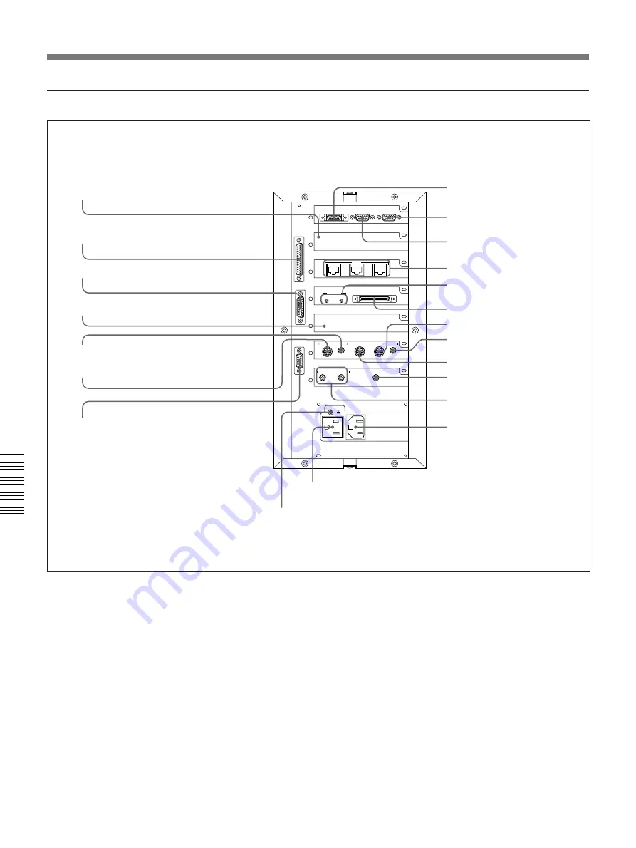
Rollabout Processor (Rear)
1
Line interface board slot
Install a line interface board (not supplied) in this slot.
2
CAMERA UNIT connector (D-sub 25-pin,
female)
Connect the camera unit to this connector.
3
AUDIO UNIT connector (D-sub 15-pin, female)
Connect the PCS-A520EK External Microphone Kit to
this connector.
4
Dual monitor board slot
Install the dual monitor board in this slot.
5
VIDEO OUT AUX jack (phono jack)
Connect a video deck to this jack to record a meeting.
6
VIDEO OUT MONITOR jack (mini DIN 4-pin)
Connect the TV monitor to this connector.
7
VID CONTROL connector (D-sub 9-pin, male)
Connect a VID-P100/P150 Video Presentation Stand
to this connector to operate the zoom from the
Rollabout Processor.
CAMERA
UNIT
AUDIO
UNIT
VID
CONTROL
AUX.CONTROL
USER DATA
PRINTER
V.35
A
B
ISDN
B
C
A
SCANNER
IR OUT
1
2
Y ⁄ C
GRAPHICS OUT
RGB
RGB
OBJECT
AUX1
AUX2
MONITOR
AUX
AUDIO OUT
NEAR
FAR
AUDIO IN
AC OUT
UNSWITCHED
MAX 2A
⁄
AC IN
GRAPHICS IN
VIDEO IN
VIDEO OUT
8
y
terminal
9
AC OUT socket
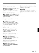
1
Line interface board slot
2
CAMERA UNIT connector
3
AUDIO UNIT connector
4
Dual monitor board slot
5
VIDEO OUT AUX jack
6
VIDEO OUT MONITOR jack
7
VID CONTROL connector
!∞
SCANNER connector
!™
USER DATA connector
!£
ISDN A/B/C jacks
!¢
IR OUT 1/2 jacks
0
PRINTER connector
!¡
AUX. CONTROL
connector
!§
VIDEO IN AUX1 jack
!¶
VIDEO IN AUX2 jack
!•
VIDEO IN OBJECT jack
!ª
AUDIO IN AUX jack
@º
AUDIO OUT FAR/NEAR
jacks
@¡
AC IN socket
Содержание PCS-5100
Страница 8: ...Features 8 Features ...


