Installation
Page 4-15
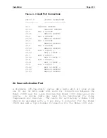
The output module which activates the air source is configured
at the factory to provide switched 12 volts DC. When using an
alternate compressed air source, current draw should be limited
to 200 ma. Inductive loads such as solenoids and relays must
have snubber diodes in parallel with their coils. The diode
anode should be connected to J8-6.
The Air Source Control connector J8 on the rear panel of the
Model
2010D
is a female type DB-9 connector.
Table 4-10
Air Source Activation Port Connections
SIGNAL SIGNATURE
2010D
J8
__________
_________________
J8-1
CHASSIS GROUND
J8-2
AIR ON HIGH (Switched DC)
J8-6
AIR ON LOW (Analog Ground)
Photometer Analog Output Connections
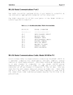
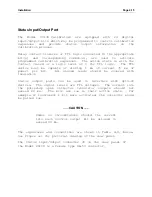
If the Photometer option is installed and the Photometer's
output is to be monitored by a strip chart recorder, datalogger
or other external device, a cable must be made with the
connections listed in the Table, below.
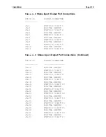
Table 4-11 Photometer Analog Output Connections
2010D
J9
SIGNAL SIGNATURE
_______
_________________
J9-1
CHASSIS GROUND
J9-2
DAS OUT 1
J9-3
DAS OUT 2
J9-4
DAS OUT 3
J9-5
RESERVED
J9-6
CHASSIS GROUND
J9-7
GROUND
J9-8
GROUND
J9-9
GROUND
Содержание 2010D
Страница 1: ...MODEL 2010D GAS DILUTION CALIBRATOR OPERATIONS MANUAL I N S T R U M E N T S...
Страница 3: ......
Страница 20: ...System Operations Page 3 2 Figure 3 1 The Model 2010D Front Panel...
Страница 42: ...Installation Page 4 15 Figure 4 1 Rear Panel...
Страница 63: ...Operation Page 5 7 Figure 5 5 The Dilution Status Screen Figure 5 6 The Ozone Status Screen...
Страница 177: ...MODEL 2010D GAS DILUTION CALIBRATOR SCHEMATICS...
Страница 178: ......
Страница 182: ...INSTRUMENTS 2548 Shell Road Units A D Georgetown Texas 78628 Phone 512 869 0544Fax 512 869 0993 sales sabio com...


