Internal UV Ozone Photometer
Page 9-22
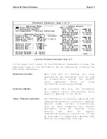
For the standard configuration, initially tune the servo loop
using the 2010
D
's "Fake Hardware" mode. In this mode, all
analog and digital I/O is replaced by simulated hardware. In
particular, care has been taken to make the photometer
simulation as close to the real thing as possible, at least
for the standard configuration with the Photometer inlet
attached to the 2010
D
's outlet manifold. The Fake Hardware
mode may be selected by typing ALT-H on an external keyboard.
When in Fake Hardware mode, it is possible to temporarily
reduce the photometer cycle time by setting the Sample Hold to
0 and Sample Measure to 1. These parameters can be changed on
page 1 of the Photometer Parameters screen. This will speed
up the testing process without affecting the actual PID
tuning.
In order to force a servo loop adjustment to be necessary,
temporarily change the Photometer's calibration by entering
new coefficients in the Photometer Calibration under the
Devices menu (after first recording the current Photometer
calibration). For example, setting the A, B and C
coefficients to 0, .95 and 0 will cause about a -5% span error
that the PID loop must adjust for. After arriving at a set of
PID constants, try varying the B coefficient and observing how
the loop responds.
Use the strip chart in the Photometer Diagnostics screen to
observe the response of the photometer as its measurement
closes in on the setpoint value. Alternatively, an external
strip chart recorder attached to a photometer DAC output could
be used to provide a more detailed picture of the response
characteristic.
Set the PID Holdoff such that the PID loop does not become
active until the Photometer's measurement has approximately
reached a final value on its own. This greatly improves
initial response time. For the standard configuration, it
takes about 10 cycles (at 16 seconds per cycle) for the
photometer's reading to stabilize after an ozone setpoint
change.
Initially, set the PID filter to about 12 and the Filter
Holdoff to about 2. This provides pre-filtering of the
Photometer's measured ozone data. It is important to remove
as much noise as possible to avoid excessive wandering of the
servo loop as it tries to correct for random noise.
Increasing the PID Filter too much could adversely affect
response time of the loop.
Содержание 2010D
Страница 1: ...MODEL 2010D GAS DILUTION CALIBRATOR OPERATIONS MANUAL I N S T R U M E N T S...
Страница 3: ......
Страница 20: ...System Operations Page 3 2 Figure 3 1 The Model 2010D Front Panel...
Страница 42: ...Installation Page 4 15 Figure 4 1 Rear Panel...
Страница 63: ...Operation Page 5 7 Figure 5 5 The Dilution Status Screen Figure 5 6 The Ozone Status Screen...
Страница 177: ...MODEL 2010D GAS DILUTION CALIBRATOR SCHEMATICS...
Страница 178: ......
Страница 182: ...INSTRUMENTS 2548 Shell Road Units A D Georgetown Texas 78628 Phone 512 869 0544Fax 512 869 0993 sales sabio com...


