Internal Calibrations
Page 8-13
[5] If the ozone standard does not incorporate automatic
temperature and pressure correction, the barometric pressure
in the room and the temperature of the gas should be
measured. Ideally, the gas temperature sensor should be
placed in the gas stream as it exits the ozone photometer,
assuring that it actually represents the temperature of the
gas in the photometer. The barometric pressure is not
likely to change during a calibration, however the gas
temperature should be measured for each calibration point.
[6] Select the method of linearization desired by selecting the
Parameters item from the calibration menu and then selecting
a method from the Linearization Method list (see Figure 8-
6).
For the ozone generator, the spline method is
recommended.
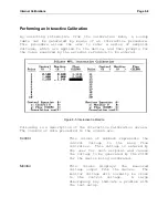
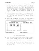
[7] Select the Interactive option from the Ozone Generator
Calibration menu. The following screen will appear:
Figure 8-7 Interactive Ozone Calibration
[8] Enter the Total Flow Rate to a flow sufficient to supply the
ozone standard (and any other analyzer that are drawing from
the outlet manifold) plus a little excess flow from the
outlet manifold’s vent. Ideally, this flow rate would be
the same total flow that is typically used during ozone and
GPT calibrations. After pressing F3 (or TAB), the
2010D
will activate the diluent and ozone MFCs to produce the
commanded total flow. Verify that there is excess flow from
the manifold vent.
Содержание 2010D
Страница 1: ...MODEL 2010D GAS DILUTION CALIBRATOR OPERATIONS MANUAL I N S T R U M E N T S...
Страница 3: ......
Страница 20: ...System Operations Page 3 2 Figure 3 1 The Model 2010D Front Panel...
Страница 42: ...Installation Page 4 15 Figure 4 1 Rear Panel...
Страница 63: ...Operation Page 5 7 Figure 5 5 The Dilution Status Screen Figure 5 6 The Ozone Status Screen...
Страница 177: ...MODEL 2010D GAS DILUTION CALIBRATOR SCHEMATICS...
Страница 178: ......
Страница 182: ...INSTRUMENTS 2548 Shell Road Units A D Georgetown Texas 78628 Phone 512 869 0544Fax 512 869 0993 sales sabio com...

