background image

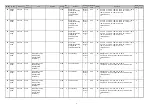
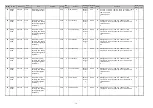
05/08

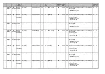
Mode

Element

Sub

element

Item

Subitem

Code

Sub-
code

Details

Default

value

Acceptable

value

RAM

Contents

Proce

dure

Servic

e UI

05

Adjustmen
t mode

Image
Processing

Range
correction
adjustment

SCN (color)

Full color/Manual
density adjustment

8362

Printed image

0

0~1

SYS 0: Background peak - Fixed

1: Background peak - Varied

1

Yes

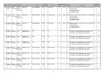
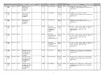
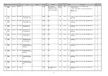
05

Adjustmen
t mode

Image
Processing

Range
correction
adjustment

SCN (color)

Full color/Manual
density adjustment

8365

User custom

0

0~1

SYS 0: Background peak - Fixed

1: Background peak - Varied

1

Yes

05

Adjustmen
t mode

Image
Processing

Backgroun
d
adjustment

SCN (color)

8370

User custom

50

0~50

SYS When the value increases, the background becomes

darker.

1

Yes

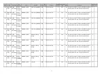
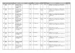
05

Adjustmen
t mode

Image
Processing

Fine
adjustment
of black
density

SCN (color)

8371

User custom

0

0~4

SYS Adjusts the black density of the scanned image. When

the value increases, the black density becomes darker.

1

Yes

05

Adjustmen
t mode

Image
Processing

RGB
conversion
method
selection

SCN (color)

8372

User custom

0

0~3

SYS Sets the color space format of the output image.

0: sRGB  1: AppleRGB  2: ROMMRGB  3: AdobeRGB

1

Yes

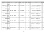
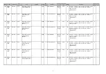
05

Adjustmen
t mode

Image
Processing

Saturation
adjustment

SCN (color)

8373

User custom

128

0~255

SYS The larger the value is, the brighter the image becomes.

The smaller the value is, the duller the image becomes.

1

Yes

05

Adjustmen
t mode

Image
Processing

Sharpness
adjustment

SCN (color)

Full color

8375

User custom

128

0~255

SYS The larger the value is, the sharper the image becomes.

The smaller the value is, the softer the image becomes
and the less moire appears.

1

Yes

05

Adjustmen
t mode

Image
Processing

Density
adjustment

SCN (color)

Manual
adjustment/Center
value

8380

User custom

128

0~255

SYS When the value increases, the image becomes darker.

1

Yes

05

Adjustmen
t mode

Image
Processing

Density
adjustment

SCN (color)

Manual
adjustment/Light step
value

8381

User custom

20

0~255

SYS Sets the changing amount per step of the density

adjustment buttons on the control panel. The larger the
value is, the lighter the image of the "light" step
becomes.

1

Yes

05

Adjustmen
t mode

Image
Processing

Density
adjustment

SCN (color)

Manual
adjustment/Dark step
value

8382

User custom

20

0~255

SYS Sets the changing amount per step of the density

adjustment buttons on the control panel. The larger the
value is, the darker the image of the "dark" step
becomes.

1

Yes

05

Adjustmen
t mode

Image
Processing

Backgroun
d offset
adjustment

SCN (color)

Automatic density
adjustment

8385

Text

128

0~255

SYS The larger the value is, the less easily the background

(low density area) is printed. The smaller the value is,
the more easily the background (low density area) is
printed.

1

Yes

42

Содержание ES9160

Страница 1: ...aintenance Manual This document is OKI DATA CONFIDENTIAL Only persons and parties authorised by OKI DATA have permissions to access this document This document should not be accessed by any parties wi...

Страница 2: ...ript is a trademark of Adobe Systems Incorporated NOVELL NetWare and NDS are trademarks or registered trademarks of Novell Inc Mylar is a registered trademark of DuPont Teijin Films U S Limited Partne...

Страница 3: ...20 240 V 8 A for its power source The equipment must be grounded for safety Select a suitable place for installation Avoid excessive heat high humidity dust vibration and direct sunlight Provide prope...

Страница 4: ...er for the LCD backlight and power supply unit Especially the board of these components should not be touched since the electric charge may remain in the capacitors etc on them even after the power is...

Страница 5: ...el For U S A and Canada 2 Explanatory label 3 Identification label For U S A Canada and EU 4 Warning for grounding wire 5 Cautionary label for laser unit 6 Warning for high temperature area fuser unit...

Страница 6: ...ithium batteries according to this manual Attention Se d barrasser de batteries et IC RAMs us s y compris les batteries en lithium selon ce manuel Vorsicht Entsorgung der gebrauchten Batterien und IC...

Страница 7: ...enden Das Ger t ist aus Sicherheitsgr nden zu erden Einen geeigneten Standort f r die Installation w hlen Standorte mit zuviel Hitze hoher Luftfeuchtigkeit Staub Vibrieren und direkter Sonneneinstrahl...

Страница 8: ...n Steuerumrichter f r die Belichtungslampe den Umrichter f r die LCD Hintergrundbeleuchtung und das Netzger t ber hren Insbesondere sollten die Platinen dieser Komponenten nicht ber hrt werden da die...

Страница 9: ...hmutzt sind und korrekt am Ger t angebracht sind 1 Klassifizierungsetikett 2 Erklarungsetikett 3 Erkennungsetikett 4 Warnung fur Erdungskabel 5 Laser Warnetikett 6 Warnung fur Bereiche mit hohen Tempe...

Страница 10: ...ithium batteries according to this manual Attention Se d barrasser de batteries et IC RAMs us s y compris les batteries en lithium selon ce manuel Vorsicht Entsorgung der gebrauchten Batterien und IC...

Страница 11: ...osition durch Laserstrahlung kommen Die Lasereinheit ist vollst ndig mit einer Schutzabdeckung versiegelt Solange ausschlie lich die Arbeitsschritte der vorgeschriebenen Anleitungen durchgef hrt werde...

Страница 12: ......

Страница 13: ...6 Lamps and heaters 3 14 3 3 7 Thermistors and thermostats 3 15 3 3 8 Transformer 3 15 3 3 9 Others 3 16 3 4 COPY PROCESS 3 17 3 4 1 General Description of Copying Process 3 17 3 5 GENERAL OPERATION...

Страница 14: ...ISASSEMBLY AND REPLACEMENT 4 1 4 1 Disassembly and Replacement of Covers 4 1 4 1 1 Front cover 4 1 4 1 2 Front upper cover 4 1 4 1 3 Front lower cover 4 2 4 1 4 Left upper cover 4 2 4 1 5 Right upper...

Страница 15: ...19 Feed cover 4 40 4 5 20 Transport roller 4 41 4 5 21 2nd transport sensor S14 4 42 4 5 22 Feed cover opening closing detection sensor S13 4 42 4 5 23 Flywheel 4 42 4 5 24 Registration roller clutch...

Страница 16: ...88 4 10 1 Reverse unit 4 88 4 10 2 Paper exit unit 4 89 4 10 3 Exit motor M10 4 90 4 10 4 Offset gate home position sensor S24 4 91 4 10 5 Exit roller 4 91 4 10 6 Reverse motor M14 4 92 4 10 7 Reverse...

Страница 17: ...ion procedure 5 28 5 12 3 Functions 5 29 5 13 List Print Mode 9S 5 30 5 13 1 Operation procedure 5 30 5 13 2 List printing 5 32 5 14 Pixel counter and its related code 5 43 5 14 1 Outline 5 43 5 15 PM...

Страница 18: ...stment of Dogleg 6 64 6 13 Adjustment of the RADF 6 66 6 13 1 Adjustment of RADF position 6 66 6 13 2 Adjustment of RADF height 6 70 6 13 3 Adjustment of skew 6 72 6 13 4 Adjustment of the leading edg...

Страница 19: ...14 7 5 4 Precautions 7 14 7 5 5 To allow the equipment to detect a recycled unit as a new one after replacement 7 15 7 6 Fuser Unit Status Detection Mode 7 16 7 6 1 General description 7 16 7 6 2 Oper...

Страница 20: ...all 8 133 8 3 15 Circuit related service call 8 136 8 3 16 Communication related service call 8 138 8 3 17 RADF related service call 8 139 8 3 18 Laser optical unit related service call 8 139 8 3 19 F...

Страница 21: ...n replacing the SLG board 9 19 9 2 8 Precautions and Procedures when replacing SRAM board 9 20 9 2 9 Procedures when replacing EEPROM 9 26 9 2 10 Firmware confirmation after the PC board HDD replaceme...

Страница 22: ...1 7 1 Procedure 11 73 11 7 2 Flow chart for correcting USB update failure 11 74 12 BACKUP FUNCTION 12 1 12 1 Data Cloning 12 1 12 1 1 General description 12 1 12 1 2 Precautions 12 1 12 1 3 Backup fil...

Страница 23: ...70 MFP The customizing ability is improved and high security performance is given by adopting a new OS New standard IEEE2600 embedded The open platform interface using Web Service is embedded The Inne...

Страница 24: ...ES9160 MFP ES9170 MFP 2012 OKI DATA CORPORATION All rights reserved FEATURES 1 2...

Страница 25: ...al scanning sensor Linear CCD sensor Scanning light source LED Reproduction ratio Actual ratio 100 0 5 Zooming 25 to 400 in increments of 1 25 to 200 when using RADF Resolution Scanning 600 dpi x 600...

Страница 26: ...memory 1GB Incl page memory HDD 60GB Paper size Drawers A3 A4 A4 R A5 R B4 B5 B5 R FOLIO 8K 16K 16K R LD LG LT LT R ST R COMPUTER 13 LG 8 5 x8 5 Non standard sizes are not available Bypass feeding A3...

Страница 27: ...or less 115 V series 200 V series Super Sleep mode 1 W or less When the damp heater switch is set to OFF and only 1 FAX line is used The electric power is supplied to the RADF ADU Finisher Job Separa...

Страница 28: ...mensional object The reversing automatic document feeder RADF only accepts paper which are not pasted or stapled Carbon paper are not acceptable either Maximum size A3 LD Eliminated portion Leading ed...

Страница 29: ...25 4 29 5 A3 LD 25 4 25 4 25 4 25 4 Paper size Model name Drawer Bypass feed PFP LCF Size specified Size not specified A4 LT B5 A5 R ST R ES9160 MFP ES9170 MFP 35 3 43 4 35 3 43 4 24 8 24 8 35 3 43 4...

Страница 30: ...rned off Finisher is not installed Paper size Model name Drawer Bypass feed PFP LCF Size specified Size not specified A4 LT B5 A5 R ST R ES9160 MFP ES9170 MFP 35 3 43 4 24 8 24 8 A4 R B5 R LT R ES9160...

Страница 31: ...ver 2008 Server 2008 R2 Windows 7 Mac OS X Ver 10 2 4 or higher Solaris SUN HP UX AIX IBM Linux SCO Resolution 600 x 600 dpi Eliminated portion Leading edges Trailing edges Side edges 4 2 2 0 mm Inter...

Страница 32: ...ution in RX Scanning Original Document Size A3 B4 A4 A4 R A5 B5 B5 R A5 R LT LT R LG LD ST ST R Computer FOLIO Speed 0 7sec per page A4 Max 50 spm ITU T No 1 A4 8 x 3 85 Text mode Gray scale 256 level...

Страница 33: ...0 x 200 dpi Super Fine 200 x 400 dpi Ultra Fine 400 x 400 dpi Internet Fax 200 dpi x 200 dpi Original Document Size A3 B4 A4 B5 A5 LT LG LD ST FOLIO Computer Mail Box User defined Max 300 boxes Data t...

Страница 34: ...are correctly co packed at the time of unpackin Unpacking setup instruction 1 set Operator s manual 1 set except for MJD Safety Information 1 manual SYS V1 0 Quick Start Guide 1 manual SYS V1 0 Operat...

Страница 35: ...025 Work Table KK 4550 Antenna GN 3010 Damp Heater Kit MF 4550 U E Scanner Kit GM 4240 Printer Kit GM 1240 Printer Scanner Kit GM 2260 Data overwrite Enabler GP 1070 Hole Punch Unit MJ 6103 N E F S Re...

Страница 36: ...or installation of the hole punch unit MJ 6103N E F S The finisher MJ 1032 is necessary for installation of the hole punch unit MJ 6007N E F S The finisher MJ 1033 is necessary for installation of the...

Страница 37: ...PORATION All rights reserved ES9160 MFP ES9170 MFP SPECIFICATIONS ACCESSORIES OPTIONS SUPPLIES 2 13 2 4 Supplies 1 U ODA ODNA E OEL D AOS Drum OD 4530 Toner cartridge PS ZT4590U PS ZT4590E PS ZT4590D...

Страница 38: ...ES9160 MFP ES9170 MFP 2012 OKI DATA CORPORATION All rights reserved SPECIFICATIONS ACCESSORIES OPTIONS SUPPLIES 2 14...

Страница 39: ...A12 H5 H6 I1 J3 G8 I2 G2 H2 H4 H1 H3 G7 F8 F11 F10 F9 F12 F7 F6 F5 F4 F3 F2 C4 C3 C5 C2 C6 C12 C11 C13 C10 C14 C1 C9 F1 E2 E1 E4 E3 G5 G6 G4 J1 G3 G1 J2 I4 I3 D2 D3 D1 C17 C17 E6 E7 B2 B1 A4 A5 A9 A2...

Страница 40: ...ATA CORPORATION All rights reserved OUTLINE OF THE MACHINE 3 2 Fig 3 2 Rear side view A13 H8 J4 A16 I5 I6 I7 D4 C18 C19 E5 H7 H8 H7 H9 H9 F14 F13 C8 C16 C7 C15 A14 A15 A13 J4 A16 I5 I6 I7 D4 C18 C19 E...

Страница 41: ...r center thermostat C5 Upper drawer tray up sensor G6 Fuser front thermostat C6 Upper drawer empty sensor G7 Center side edge thermistor C7 Upper tray up motor G8 Exit sensor C8 Upper drawer feed clut...

Страница 42: ...S9170 MFP 2012 OKI DATA CORPORATION All rights reserved OUTLINE OF THE MACHINE 3 4 3 2 Electric Parts Layout 1 Scanner unit control panel Fig 3 3 M1 S5 S4 S1 S3 KEY TCP DSP S7 LEDB S6 DH1 DH2 CCD SLG...

Страница 43: ...3 2012 OKI DATA CORPORATION All rights reserved ES9160 MFP ES9170 MFP OUTLINE OF THE MACHINE 3 5 2 Power supply developer unit Fig 3 4 SW1 DH3 ERS THMS4 SW3 EPU SW2 LVPS HVPS M2 THMO3 S8...

Страница 44: ...ES9170 MFP 2012 OKI DATA CORPORATION All rights reserved OUTLINE OF THE MACHINE 3 6 3 Laser unit fuser unit toner cartridge Fig 3 5 THMS3 THMS2 THMS1 S9 THMO1 LAMP2 SW4 LAMP1 LAMP3 M4 CTIF CTRG M3 LDR...

Страница 45: ...3 2012 OKI DATA CORPORATION All rights reserved ES9160 MFP ES9170 MFP OUTLINE OF THE MACHINE 3 7 4 Drive unit Fig 3 6 MOT2 M5 HDD FUS M7 M8 M6 LGC SYS S25...

Страница 46: ...MFP ES9170 MFP 2012 OKI DATA CORPORATION All rights reserved OUTLINE OF THE MACHINE 3 8 5 Automatic duplexing unit transfer unit exit unit Fig 3 7 M14 M10 S24 CLT1 S10 M13 S11 SOL1 S23 SW5 M9 CLT2 S2...

Страница 47: ...3 2012 OKI DATA CORPORATION All rights reserved ES9160 MFP ES9170 MFP OUTLINE OF THE MACHINE 3 9 6 Bypass feed unit Fig 3 8 S12 SFB CLT3...

Страница 48: ...ES9160 MFP ES9170 MFP 2012 OKI DATA CORPORATION All rights reserved OUTLINE OF THE MACHINE 3 10 7 Drawer unit Fig 3 9 S13 S20 S19 S17 S16 CLT5 S18 S14 M12 SW7 SW6 S15 CLT4 M11 CLT6 CLT7...

Страница 49: ...6 4 14 M8 MAIN MOT Main motor Driving the drum developer unit fuser unit registration roller transport rollers feed rollers and pickup rollers Fig 3 6 14 21 M9 TRU FAN TRU fan Assisting the paper sep...

Страница 50: ...drawer tray up sensor Position detection of the lifting tray of the lower drawer Fig 3 9 16 18 S20 EMP L SNR Lower drawer empty sensor Paper presence absence detection in the lower drawer Fig 3 9 16...

Страница 51: ...roller Fig 3 9 16 5 CLT5 CST L FEED CLT Lower drawer feed clutch Driving the lower drawer pickup roller Fig 3 9 16 5 CLT6 TR U CLT High speed transport clutch Driving with high speed for the transport...

Страница 52: ...3 3 12 12 SNS PWA F SNS H sync signal detection PC board SNS board Detection of the laser beam position Fig 3 5 11 1 SYS PWA F SYS System control PC board SYS board Controlling the whole system and im...

Страница 53: ...ig 3 3 12 22 THMS1 THMS C HTR Center thermistor Detecting the surface temperature at fuser roller center for controlling the temperature of the center heater lamp Fig 3 5 31 31 THMS2 THMS S HTR Side t...

Страница 54: ...TCP TCP Touch panel Displaying and entering various kinds of information Fig 3 3 3 22 3 23 HDD HDD Hard disk Storing the program data and image data Fig 3 6 9 6 LEDB PWA LED LED board Controlling the...

Страница 55: ...ressure 4 Data writing The electrical signals are converted into light signal laser emission which exposes the surface of the photoconductive drum 10 Cleaning Scrapes off the residual toner from the d...

Страница 56: ...ts reserved OUTLINE OF THE MACHINE 3 18 3 5 GENERAL OPERATION 3 5 1 Overview of Operation Operation of equipment Operation during initializing pre running and ready Copying operation Drawer feed copyi...

Страница 57: ...The exposure lamp is turned OFF READY WARMING UP is displayed 2 Pre running operation The pre running operation is started when the temperature of the fuser roller surface reaches a certain temperatu...

Страница 58: ...ion roller The registration sensor is turned ON and aligning is performed Drawer feed clutch OFF after a certain period of time 3 After the carriage operation Registration clutch ON after a certain pe...

Страница 59: ...to rotate Aligning operation Paper reaches the registration roller After a certain period of time the bypass feed clutch OFF 4 Hereafter the operation 3 through 6 of P 3 20 3 Drawer feed copying Upper...

Страница 60: ...er 2 Abnormality not cleared without turning OFF the door switch D Misfeed in equipment E Replace the toner cartridge F EPU not installed properly 3 Abnormality not cleared without turning OFF the mai...

Страница 61: ...aper Cleared by turning the drawer open close Tray up sensor is turned ON in a fixed period of time The tray motor stops At this time if the empty sensor is ON It is judged that there is paper OFF It...

Страница 62: ...ey copy counter displayed Copying operation disabled When the counter is pulled out during copying Copying is stopped when the key copy counter is pulled out Set key copy counter displayed Copying ope...

Страница 63: ...sensor ON If the reverse sensor is not turned ON after the regulation time Paper jam E570 The copying operation is stopped Reverse sensor detects jamming of the tailing edge of paper Exit sensor OFF L...

Страница 64: ...am E110 During paper transporting from ADU ADU entrance exit sensors do not detect the paper at the fixed timing Paper jam E510 or E520 The 1st 2nd transport sensor and each sensors of PFP LCF are not...

Страница 65: ...nk with messages explaining the condition of the equipment in the LCD panel When paper jams and Call for service occur error codes are also displayed to notify users of the problem This equipment has...

Страница 66: ...ES9160 MFP ES9170 MFP 2012 OKI DATA CORPORATION All rights reserved OUTLINE OF THE MACHINE 3 28 3 6 2 Description of Operation 1 Dot matrix LCD circuit 1 Structure Fig 3 14 800 x R G B x 480 dots...

Страница 67: ...s performed converting the optical image data into an electrical analog signal This analog signal is changed to a digital signal which then undertakes various corrective processes necessary for image...

Страница 68: ...iage 1 Exposure lamp EXP LED Reflector Mirror 1 Carriage 2 Mirror 2 Mirror 3 Lens unit CCD driving PC board CCD Scanning section control PC board SLG Automatic original detection sensor S1 5 LED board...

Страница 69: ...riginal glass by the carriage Do not use such solvents as alcohol when cleaning the surface of the RADF original glass because it is coated so as not to be scratched by originals 2 Carriage 1 Carriage...

Страница 70: ...irror 3 is led to the CCD placed at the focal point of the lens which is fixed in a position 5 CCD driving PC board CCD Processes such as signal amplification and A D conversion are applied on the ele...

Страница 71: ...TION All rights reserved ES9160 MFP ES9170 MFP OUTLINE OF THE MACHINE 3 33 8 LED LDB Controls lighting of the exposure lamp EXP It is installed on the rear side since the scanner thickness is reduced...

Страница 72: ...are detected when the carriage 1 passes the carriage home position sensor S7 When the START button is pressed the both carriages start to move and scan the original on the glass Scanning of an origin...

Страница 73: ...ng to the digital image signals transmitted from the LGC board to create the latent image Image signal is converted into the light emission signal of the laser diode on the laser driving PC board LDR...

Страница 74: ...danger of being exposed to laser radiation The following cautionary label for the laser is attached to the right front cover Fig 3 23 Cautions Avoid expose to laser beam during service This equipment...

Страница 75: ...rubber 14 Upper drawer pickup roller 2 Registration roller metal 15 Upper drawer feed roller 3 Registration sensor S22 16 Upper drawer separation roller 4 1st 2nd transport sensor S21 17 Lower drawer...

Страница 76: ...E MACHINE 3 38 Paper feeding section drive system Rear side Fig 3 25 Registration roller metal Registration roller rubber Main motor Registration roller clutch Hi speed clutch Low speed clutch Bypass...

Страница 77: ...drawer empty sensor S17 S20 Upper Lower drawer feed clutch CLT4 CLT5 Bypass unit Bypass feed roller PM parts Bypass separation pad PM parts Bypass paper sensor S12 Bypass feed clutch CLT3 Paper width...

Страница 78: ...he bypass feed roller and pressed to this roller with spring force This pad prevents more than one sheet of paper from being fed simultaneously with its frictional surface 8 Bypass paper sensor S12 Th...

Страница 79: ...ve from these clutches rotates the pickup rollers so as to pick up paper 15 Hi speed clutch CLT6 Drives the Transport roller at high speed by transmitting the drive from the main motor 16 Low speed cl...

Страница 80: ...equipment side When the paper holding lever is laid down to the equipment side the paper holding guide lifts up the paper as shown in the figure so as to contact the paper with the bypass feed roller...

Страница 81: ...ay up motor driving force Then the drawer tray lifts up and paper feeding is enabled When the drawer feed clutch is turned ON the drive from the main motor is transmitted Then the feed roller and pick...

Страница 82: ...further and the upper sheet is transported in the direction of black arrow since the frictional force between two sheets is small Example When only one sheet enters into the separation roller section...

Страница 83: ...MFP ES9170 MFP OUTLINE OF THE MACHINE 3 45 4 Operation of clutch The power ON OFF of transport clutch and the operation of transport roller are as follows Transport roller High speed clutch Low speed...

Страница 84: ...enters the ready state During the ready mode the tray stays at the raised position When a drawer is inserted or removed in the ready state the tray is raised again and checks the presence absence of...

Страница 85: ...ickup roller and feed roller rotate to start paper feeding The leading edge of paper turns the registration sensor ON and the paper is aligned by the registration rollers The feed clutch is turned OFF...

Страница 86: ...drawer and bypass unit and registration roller The drive system is driven by the rotation of the main motor Fig 3 30 Main motor M8 Toner motor M4 Registration roller clutch CLT2 Registration roller By...

Страница 87: ...or through the gears and timing belt to the fuser unit gears The bridge unit the job separator and the offset tray are driven by transmitting from the fuser unit 4 Registration roller drive Drives the...

Страница 88: ...xplains about the area around the drum drum itself image processing their parts and control circuits Fig 3 31 Cleaning blade Toner recovery auger Toner cartridge interface board CTIF board Drum thermi...

Страница 89: ...r unit Drum PM parts Main charger PM parts Cleaner Cleaning blade PM parts Recovery blade PM parts Needle electrode PM parts Discharge LED ERS Transfer roller unit Transfer roller PM parts Separation...

Страница 90: ...ed corona discharge At the same time a control bias is applied to the main charger grid to control the charging amount In a dark place negative charge is evenly applied onto the drum surface by the co...

Страница 91: ...tion and the residual charge on the drum surface is neutralized and eliminated The electrical potential of the drum surface is fixed to a certain amount before the drum is charged 6 Drum thermistor Th...

Страница 92: ...as a recovered toner supply mechanism which recovers the recovered toner scraped off by the drum cleaning blade and recycles the recovered toner The developer unit is driven by the main motor to rotat...

Страница 93: ...eloper unit Developer material PM parts Mixers 1 2 and 3 Developer sleeve Magnet roller Doctor blade Auto toner sensor S8 Drum thermistor THMS4 EPU memory board EPU Recovered toner supply mechanism To...

Страница 94: ...ith sufficient time Developer sleeve Magnetic roller This is an aluminum roller with a magnet inside The magnet works to absorb the developer material and forms the magnetic brush The magnet is fixed...

Страница 95: ...with developer material by the mixer 3 The mixer 3 is mounted exclusively for the recovered toner to mix it with sufficient time On the other hand the toner fresh transported into the developer unit f...

Страница 96: ...transported paper The paper is then transported to the paper exit section after completion of fusing The fuser unit consists of the heater lamps fuser roller pressure roller separation fingers thermis...

Страница 97: ...is fuser unit to enable envelopes to pass through 4 Separation fingers The separation fingers are installed five above the pressure roller and five above the fuser roller in order to separate the pape...

Страница 98: ...e paper is transported to the inner tray paper exiting options or ADU through the exit roller In addition the heater lamps in the fuser roller do not structurally rotate 3 heater lamps having differen...

Страница 99: ...rol circuit does not function for some reason and the fuser roller is abnormally overheated as the result a relay OFF circuit transmits a relay OFF signal to turn off the relay and to turn the power O...

Страница 100: ...unction and the paper position is shifted apart from one another back and forth The reverse section is a path only for switchbacking to the ADU to enhance the high speed printing The reverse section h...

Страница 101: ...edge of the reversed paper at duplex printing as well 4 Reverse motor M14 The reverse motor is a stepping motor which drives the reverse roller however this motor rotates reversely to switchback when...

Страница 102: ...1 Exit Motor The figure shown below is the layout of the driving gears of the exit roller Fig 3 38 2 Reverse Motor The figure shown below is the layout of the driving gears of the reverse roller Fig...

Страница 103: ...I DATA CORPORATION All rights reserved ES9160 MFP ES9170 MFP OUTLINE OF THE MACHINE 3 65 3 Offset gate motor The figure shown below is the layout of the driving gears of the offset gate Fig 3 40 Forwa...

Страница 104: ...is equipment is a unit to transport the paper which is switchbacked at the paper exit section reverse section and transported reversed to the registration roller again Fig 3 41 ADU Reverse roller Reve...

Страница 105: ...alled to the rear frame of the equipment 2 ADU clutch CLT1 Transmits the drive from the ADU motor M5 to the ADU lower transport roller 3 ADU entrance sensor S11 Detects the paper transported in the AD...

Страница 106: ...x printing There are three methods of judging a paper jam 1 whether the ADU entrance sensor is turned ON or not in a specified period of time after the switchback to the ADU started E510 2 whether the...

Страница 107: ...otor rotates in the direction A the ADU upper transport roller is rotated with the drive of the gears and belt and thus the paper is transported When the ADU clutch is turned ON the ADU lower transpor...

Страница 108: ...tch line Power supply used in the entire equipment during image forming process being supplied via the interlock switch Two kinds of voltage 5VD and 24VD are output only when the main power switch of...

Страница 109: ...FF button on the control panel is pressed during the super sleep mode a super sleep mode shifting recovering signal SYS EN is output from the SYS board and then voltage starts being supplied to all th...

Страница 110: ...mode Since 5VB 5VD 12VB and 24V DC voltages are not supplied but 12VA 5VA and 5VS DC voltages only the equipment does not enter into the ready state Super Sleep mode Only DC voltage and 5VS are output...

Страница 111: ...to the finisher 5VB CN419 Pins 1 and 2 Output to the SLG board 5VB CN419 Pin 4 Output to the RADF 2 12V 12VA CN418 Pin 5 Output to the SYS board 12VB CN419 Pin 5 Output to the SLG board The following...

Страница 112: ...VA CN415 For the LGC board FUS board PFP LCF via LGC board Bridge unit Job separator Offset tray via LGC board finisher 5VB CN419 For the SLG board RADF 5VB 12VB Connector Destination Voltage CN415 Fo...

Страница 113: ...er Tray up motor TRU fan Switching regulator cooling fan Auto toner sensor Upper drawer feed clutch Lower drawer feed clutch Registration roller clutch High speed transport clutch Low speed transport...

Страница 114: ...ES9160 MFP ES9170 MFP 2012 OKI DATA CORPORATION All rights reserved OUTLINE OF THE MACHINE 3 76...

Страница 115: ...ers 4 1 1 Front cover 4 1 2 Front upper cover 1 Open the front cover Fig 4 1 2 Slide the upper hinge to the left side while holding it down and then take off the upper hinge 3 Take off the lower hinge...

Страница 116: ...er cover 2 Remove 2 screws and then take off the control panel unit 3 Disconnect the USB port from the front lower cover Fig 4 4 4 Remove 2 screws and pull the left side of the front lower cover towar...

Страница 117: ...fting it up Remarks When installing the rear cover hang the 3 hooks of the rear cover on the frame of the equipment and then hang the 3 hooks on the holes of the upper rear cover to fix it Then tighte...

Страница 118: ...cover 4 Take off the rear cover P 4 3 4 1 6 Rear cover 5 Remove 2 screws and take off the upper rear cover Fig 4 10 1 Remove 1 screw and then take off the left rear cover by releasing 2 hooks Remarks...

Страница 119: ...left rear cover P 4 4 4 1 8 Left rear cover 2 Take off the inner tray P 4 4 4 1 9 Inner tray 3 Take off the tray back cover Fig 4 14 1 Open the automatic duplexing unit 2 Remove 1 screw and then take...

Страница 120: ...cover 1 1 Fig 4 16 4 Remove 1 screw and take off the right rear cover 2 1 Fig 4 17 1 Take off the front cover P 4 3 4 1 6 Rear cover 2 Take off the process unit P 4 64 4 8 1 Process unit 3 Pull out th...

Страница 121: ...er tray 2 Take off the right front cover P 4 6 4 1 14 Right front cover 3 Remove 4 screws Disconnect 3 connectors from the left front cover and then take off the left front cover Fig 4 19 1 Remove the...

Страница 122: ...l unit 1 Take off the front upper cover P 4 1 4 1 2 Front upper cover 2 Lower the control panel 1 and remove 2 screws Fig 4 21 3 Release the hook and then take off the control panel unit 1 Fig 4 22 4...

Страница 123: ...CORPORATION All rights reserved ES9160 MFP ES9170 MFP DISASSEMBLY AND REPLACEMENT 4 9 5 Remove 1 screw and take out the clamp Fig 4 24 6 Disconnect 1 connector and then take off the control panel uni...

Страница 124: ...SASSEMBLY AND REPLACEMENT 4 10 4 2 2 Display board DSP 1 Take off the control panel unit P 4 8 4 2 1 Control panel unit 2 Remove 9 screws and take off the hinge bracket 1 Fig 4 26 3 Disconnect 5 conne...

Страница 125: ...the control panel unit P 4 8 4 2 1 Control panel unit 2 Remove 7 screws and take off the hinge bracket 1 Fig 4 28 3 Disconnect 1 connector and remove 12 screws Take off the KEY board 2 Fig 4 29 1 Take...

Страница 126: ...160 MFP ES9170 MFP 2012 OKI DATA CORPORATION All rights reserved DISASSEMBLY AND REPLACEMENT 4 12 4 2 5 Control panel cover 1 Release the 4 latches 1 and take off the control panel cover 2 Fig 4 31 2...

Страница 127: ...ve 2 screws and take off the fixing bracket Fig 4 32 3 Take off the original glass Notes When installing fit 2 small protrusions of the original glass in the groove of the equipment and fix the origin...

Страница 128: ...1 2 3 C R B LT series APS 1 3 C R 1 Take off the lens cover P 4 13 4 3 2 Lens cover 2 Disconnect 1 connector and remove 1 screw Take off APS sensor Fig 4 35 3 Disconnect 1 connector each release 2 lat...

Страница 129: ...or each APS sensor Take off 3 APS sensors Fig 4 38 1 Take off the original glass P 4 13 4 3 1 Original glass 2 Take off the front upper cover P 4 1 4 1 2 Front upper cover 3 Rotate the drive pulley an...

Страница 130: ...3 5 Lens unit 5 Disconnect the harness Notes When installing the harness be careful not to insert it at an angle Fig 4 41 1 Take off the lens cover P 4 13 4 3 2 Lens cover 2 Remove 1 screw and take of...

Страница 131: ...sure that the harness 1 of the APS sensor comes over the lens unit 2 2 See 6 9 2 for the adjustment procedure 3 Do not touch the 8 screws shown with the arrows when replacing the lens unit 4 Handle th...

Страница 132: ...4 Remove 2 screws and take off the scan motor with the whole bracket Fig 4 48 Notes When installing the scan motor use the belt tension jig spring The procedure is as follows 1 Temporarily fix the sc...

Страница 133: ...s P 4 13 4 3 1 Original glass 2 Take off the upper rear cover P 4 4 4 1 7 Upper rear cover 3 Take off the front upper cover P 4 1 4 1 2 Front upper cover 4 Release the harness from 1 harness clamp Fig...

Страница 134: ...oard 1 Notes Be careful not to apply load to the LED board when disconnecting the connector See the following chapter for the installation procedure P 4 23 4 3 9 Installing the lamp harness Fig 4 53 8...

Страница 135: ...te the carriage 1 in the direction shown in the figure at right not to touch the mirror Then take off the carriage 1 Notes When replacing the mirror 1 replace the carriage 1 together with mirror 1 Mir...

Страница 136: ...ND REPLACEMENT 4 22 4 3 8 LED driving PC board LEDB 1 Take off the rear cover P 4 3 4 1 6 Rear cover 2 Disconnect 3 connectors Notes When installing the harness be careful not to insert it at an angle...

Страница 137: ...NT 4 23 4 3 9 Installing the lamp harness 1 Install the harness to 2 harness clamps and wire it under carriage 2 Fig 4 61 2 Rotate the drive pulley and move the carriage 1 to the left side Fig 4 62 3...

Страница 138: ...ess with 1 clamp and fold the harness back After installing move carriage 1 to the left edge and confirm that there is no abnormality such as a twisted lamp harness Fig 4 64 5 Install the harness in t...

Страница 139: ...3 Fig 4 66 3 Detach the tension springs of the front and rear sides 4 Remove the carriage wires Fig 4 67 5 Take off carriage 2 by rotating it as shown in the figure on the right without touching the...

Страница 140: ...rear cover 2 Disconnect 1 connector Release the latches and take off the platen sensor 3 Remove the seal on the carriage home position sensor 4 Disconnect 1 connector Release the latches and take off...

Страница 141: ...er 2 Disconnect 2 connectors from the LGC board Notes Connect the flat harness to the LGC board with its electrode side down An error CA20 will be displayed if the connection is incorrect Fig 4 71 3 T...

Страница 142: ...or stain on the slit glass of the laser optical unit 2 Pay close attention not to make an impact or vibration on the laser optical unit because it is a precise apparatus 3 Place the removed laser opti...

Страница 143: ...er 4 5 2 Drawer feeding unit 1 Pull out the drawer until it comes to a stop 2 Remove 1 screw and the stopper 3 Take off the drawer Fig 4 77 1 Take off the drawer P 4 29 4 5 1 Drawer 2 Open the feed co...

Страница 144: ...29 4 5 2 Drawer feeding unit 2 Disconnect the connector and release the 3 latches to take off the tray up sensor Fig 4 79 1 Take off the drawer feeding unit P 4 29 4 5 2 Drawer feeding unit 2 Remove...

Страница 145: ...Pull up the paper stock sensor arm 3 Disconnect the connector and release the 3 latches to take off the paper stock sensor Fig 4 82 1 Take off the drawer feeding unit P 4 29 4 5 2 Drawer feeding unit...

Страница 146: ...paration roller 2 Remove the clip and take off the feed roller Fig 4 86 1 Take off the drawer feeding unit P 4 29 4 5 2 Drawer feeding unit 2 Press the pickup roller and lift the rear pickup arm 3 Sli...

Страница 147: ...Fig 4 88 1 Take off the drawer feeding unit P 4 29 4 5 2 Drawer feeding unit 2 Remove 2 screws and take off the clutch plate Fig 4 89 3 Disconnect 1 connector and take off the upper lower drawer feed...

Страница 148: ...tray 1 Take off the transfer unit P 4 63 4 7 17 Transfer unit 2 Open the bypass tray and then remove the stopper by twisting it for 90 degrees Fig 4 91 3 Remove 1 screw and then take off the link arm...

Страница 149: ...FB 5 Disconnect 1 connector and then take off the bypass tray downward obliquely Fig 4 94 1 Take off the bypass tray P 4 34 4 5 10 Bypass tray 2 Remove 3 screws and take off the bypass tray upper cove...

Страница 150: ...then take off the paper width detection PC board Fig 4 97 1 Take off the automatic duplexing unit P 4 97 4 11 1 Automatic Duplexing Unit ADU 2 Release 2 latches and then take off the spring holder Fi...

Страница 151: ...oller Bypass feed clutch CLT3 1 Take off the bypass feed unit P 4 36 4 5 12 Bypass feed unit 2 Remove 1 clip and then slide the bypass feed roller Fig 4 100 3 Take off the bypass separation pad arm Fi...

Страница 152: ...at the rotation stopper is inserted in the hole of the guide securely Fig 4 103 4 Remove 1 clip and 2 bushings Then take off the bypass feed roller and the bypass feed clutch Fig 4 104 1 Take off the...

Страница 153: ...U 3 Remove 1 screw and then take off the registration guide by sliding it Notes When installing the registration guide be sure that the 2 films are attached at the positions shown in the figure Fig 4...

Страница 154: ...ed cover 1 Take off the registration guide P 4 39 4 5 16 Registration guide 2 Take off the actuator 3 Release 3 latches and then take off the 1st transport sensor Fig 4 109 1 Open the feed cover and t...

Страница 155: ...T6 Low speed clutch CLT7 3 Take off the feed cover P 4 40 4 5 19 Feed cover 4 Remove 2 screws and then take off the stay Fig 4 112 5 Remove 1 screw and then slide the paper guide B to the rear side 6...

Страница 156: ...4 41 4 5 20 Transport roller 2 Take off the actuator 3 Release 3 latches and then take off the 2nd transport sensor Fig 4 115 1 Take off the transport roller P 4 41 4 5 20 Transport roller 2 Release...

Страница 157: ...LT2 1 Take off the flywheel P 4 42 4 5 23 Flywheel 2 Remove 2 screws and then take off the clutch cover Notes Match the rotation stopper of the clutch with the position shown in the figure for assembl...

Страница 158: ...cover 3 Disconnect 1 connector and take off the harness clamp from the bracket Fig 4 120 4 Remove 2 screws and take off the upper tray up motor along with the bracket Fig 4 121 5 Remove 2 screws and...

Страница 159: ...ch CLT7 1 Pull out the upper drawer 2 Take off the rear cover P 4 3 4 1 6 Rear cover 3 Disconnect 1 connector and then take off the upper drawer detection switch Fig 4 123 1 Take off the rear cover P...

Страница 160: ...with the position shown in the figure for assembling Fig 4 126 5 Remove 1 bushing and gear 6 Disconnect 1 connector and then take off the Hi speed clutch Notes Match the rotation stopper of the clutch...

Страница 161: ...ector and then take off the lower drawer detection switch Fig 4 129 1 Pull out the lower drawer 2 Take off the rear cover P 4 3 4 1 6 Rear cover 3 Disconnect 1 connector and take off the harness clamp...

Страница 162: ...tion to the size length of the screws If incorrect ones are used the motor could be damaged Fig 4 132 1 Take off the transfer unit P 4 63 4 7 17 Transfer unit 2 Remove 1 screw and then take off the br...

Страница 163: ...cess unit P 4 52 4 7 1 Process unit 2 Take off the automatic duplexing unit P 4 97 4 11 1 Automatic Duplexing Unit ADU 3 Take off the registration roller clutch P 4 43 4 5 24 Registration roller clutc...

Страница 164: ...and then take off the main motor Fig 4 138 1 Take off the rear cover P 4 3 4 1 6 Rear cover 2 Disconnect 1 connector 3 Remove 1 screw and then take off the toner motor together with its bracket Notes...

Страница 165: ...motor drive unit 1 Notes When the bracket in the main motor drive unit 1 is assembled adjust the tension following the procedure below 1 Take off the rear cover 2 Remove the spring from the ADU motor...

Страница 166: ...Open the automatic duplexing unit 2 Open the front cover and take off the toner cartridge 3 Loosen 2 screws and pull out the process unit Fig 4 144 1 Take off the process unit P 4 52 4 7 1 Process uni...

Страница 167: ...Remove 2 screws Then take off the process unit front cover Notes When installing the process unit front cover wire the harness correctly in order not to contact the gears and harness of the process u...

Страница 168: ...areful not to touch or scratch the drum surface at this time 2 Do not deform the Guide film by touching this Fig 4 149 Fig 4 150 1 Take off the drum cleaner unit P 4 52 4 7 2 Drum cleaner unit 2 Relea...

Страница 169: ...1 Take off the discharge LED unit P 4 54 4 7 3 Discharge LED 2 Pull out the main charger and take it off by sliding it to the rear side Notes Be careful not to touch or scratch the drum surface at thi...

Страница 170: ...o take it off Fig 4 155 1 Take off the main charger grid and main charger cleaner P 4 55 4 7 5 Main charger grid P 4 56 4 7 6 Main charger cleaner 2 Take off the terminal covers of both front and rear...

Страница 171: ...Take off the drum Notes 1 Be careful not to touch spit or scratch the drum surface 2 Avoid direct light Place the drum in a dark place immediately after taking off 3 Be careful not to touch or scratc...

Страница 172: ...inger units 2 pc Notes 1 When replacing the drum separation fingers make sure that the drum has been taken off first since the fingers may scratch the drum surface Fig 4 160 3 Remove the spring and ta...

Страница 173: ...the cleaner unit be careful of the following in order not to damage the films attached on the toner recovery auger 1 Do not use an air blower for cleaning Use a vacuum cleaner 2 When using a vacuum cl...

Страница 174: ...NT 4 60 4 7 13 TRU fan M9 3 Release 1 hook and then take off the filter cover Fig 4 165 4 Take off the ozone filter Fig 4 166 1 Take off the transfer unit P 4 63 4 7 17 Transfer unit 2 Remove 1 screw...

Страница 175: ...then take off the inner duct Fig 4 168 4 Take off the TRU fan Fig 4 169 1 Open the automatic duplexing unit 2 Release the hook on the rear side and then take off the transfer roller unit Notes 1 Be ca...

Страница 176: ...lers and 2 bushings from the transfer roller Notes When installing the bushings and gear pay attention to the direction of them Fig 4 172 1 Take off the transfer roller unit P 4 61 4 7 14 Transfer rol...

Страница 177: ...7 18 Temperature humidity sensor S25 1 Take off the automatic duplexing unit P 4 97 4 11 1 Automatic Duplexing Unit ADU 2 Take off 2 brackets by removing 2 screws each 3 Disconnect 1 connector and the...

Страница 178: ...ights reserved DISASSEMBLY AND REPLACEMENT 4 64 4 8 DEVELOPMENT SYSTEM 4 8 1 Process unit 1 Open the automatic duplexing unit 2 Open the front cover and take off the toner cartridge 3 Loosen 2 screws...

Страница 179: ...Take out the drum cleaner unit from the process unit so that only the developer unit will be left in it P 4 52 4 7 2 Drum cleaner unit Notes 1 Be careful not to touch or scratch the drum surface at t...

Страница 180: ...ial from rear side Notes 1 When removing the developer material be careful not to drop the developer material on the gears of the developer unit 2 When cleaning the developer unit never attempt to use...

Страница 181: ...er material P 4 65 4 8 3 Removing developer material 2 Place the developer unit upside down Disconnect 2 connectors Fig 4 183 3 Remove 1 screw Then take off the EPU memory board Fig 4 184 1 Remove the...

Страница 182: ...by rotating it Fig 4 186 1 Remove the developer material P 4 65 4 8 3 Removing developer material 2 Disconnect 1 connector remove 1 screw and take off the drum thermistor Fig 4 187 1 Remove the develo...

Страница 183: ...ews on both ends of the doctor sleeve are removed be sure to adjust the doctor sleeve gap 0 45 0 05 mm after assembling Fig 4 191 6 Remove 1 screw and plate spring 7 Remove 1 screw and take off the po...

Страница 184: ...EPLACEMENT 4 70 8 Remove 2 screws and take off the bracket Fig 4 193 9 Remove 1 E ring and take off the guide roller on the front side Fig 4 194 10 Remove 1 E ring Remove the arm and cam Fig 4 195 11...

Страница 185: ...1 bearing and the bracket Fig 4 197 13 Take off 3 gears and 1 timing belt Fig 4 198 14 Remove 1 E ring 1 pin and 1 pulley 15 Take off the guide roller on the rear side Fig 4 199 16 Remove the seal on...

Страница 186: ...AND REPLACEMENT 4 72 4 8 9 Mixer 17 Take off the developer sleeve Fig 4 201 1 Take off the developer sleeve P 4 68 4 8 8 Guide roller Developer sleeve 2 Take off the doctor sleeve Fig 4 202 3 Remove 2...

Страница 187: ...al Fig 4 204 5 Take off the mixers 2 and 3 Fig 4 205 6 Remove 2 bushings and 2 oil seals on the front side Replacement of Oil Seal P 4 74 4 8 10 Replacement of oil seal Fig 4 206 7 Remove the end sect...

Страница 188: ...eplacement of Oil Seal P 4 74 4 8 10 Replacement of oil seal Fig 4 209 1 Insert a fine screwdriver into the depression of the oil seal to take it out 2 Push in a new oil seal parallel to the frame or...

Страница 189: ...ser unit as it may become very hot Fig 4 211 Notes To store the removed fuser unit for a long period follow the procedure below 1 Open the front cover 2 Take off the pressure release metal plate front...

Страница 190: ...r 2 Notes When installing the rear cover 1 make sure that the harness is not caught Install the rear cover 1 with the ground leaf spring 3 outside of it as shown in the right hand figure Fig 4 214 4 R...

Страница 191: ...eparation finger 1 Take off the fuser roller unit P 4 76 4 9 2 Fuser roller unit Pressure roller unit 2 Remove 1 screw and take off the thermostat cover 1 Fig 4 216 3 Remove 3 screw and take off the s...

Страница 192: ...pushing strongly 2 When installing the heater lamps refer to the installation procedure P 4 79 4 9 5 Heater lamp 3 When installing the fuser roller be careful not to deform the thermistor 4 When inst...

Страница 193: ...2 When installing the heater lamps do not mix up the types of heater lamps The shapes and screw holes of each lamp vary Install the heater lamps while referring to the figure at right 3 Install the h...

Страница 194: ...nit 1 upside down 3 Remove 2 screws and then take off the harness cover 2 Notes When installing the harness cover 2 make sure that the harness is not caught Fig 4 225 4 Take out the thermistor by remo...

Страница 195: ...ide thermistor and edge thermistor by the length of each harness Fig 4 227 1 Take off the fuser roller unit P 4 76 4 9 2 Fuser roller unit Pressure roller unit 2 Place the fuser roller unit 1 upside d...

Страница 196: ...EMENT 4 82 Notes Do not loosen the 2 red screws fixing the thermostat 1 Fig 4 230 5 Remove 1 screw and take off the thermostat cover 1 Fig 4 231 6 Remove 2 screws and then take off the fuser center th...

Страница 197: ...4 2012 OKI DATA CORPORATION All rights reserved ES9160 MFP ES9170 MFP DISASSEMBLY AND REPLACEMENT 4 83 Notes Wire the harness as shown in the figure and fix it with clamp securely Fig 4 233 1...

Страница 198: ...off the pressure roller unit P 4 76 4 9 2 Fuser roller unit Pressure roller unit 2 Remove 3 screws and take off the entrance guide Fig 4 234 3 Take off the front cover Fig 4 235 4 Disconnect 1 connect...

Страница 199: ...installing the spring catch the spring on the hook in the middle Fig 4 238 6 Remove 4 screws and then take off 2 stoppers 7 Pull out the pressure roller Fig 4 239 8 Remove 2 E rings and the bearings o...

Страница 200: ...oller unit P 4 76 4 9 2 Fuser roller unit Pressure roller unit 2 Remove 1 screw and then take off the sensor cover Fig 4 241 3 Remove the seal 1 4 Disconnect 1 connector 2 and then take off the exit s...

Страница 201: ...P 4 75 4 9 1 Fuser unit 2 Remove 1 screw and take off the rear cover 1 3 Disconnect 1 connector 2 Notes When installing the rear cover 1 make sure that the harness is not caught Install the rear cove...

Страница 202: ...en handling the fuser unit as it may become very hot 2 Remove 3 screws from the left side of the reverse section and then take off the cover Fig 4 246 3 Take off the connecting port cover P 4 5 4 1 12...

Страница 203: ...erform Step 2 before removing the reverse unit Fig 4 249 Notes When installing the reverse unit engage the arm of the offset gate motor at the front of the reverse unit and the holder of the paper exi...

Страница 204: ...252 3 Release the harness from the harness clamp Remove 1 screw and take off the motor cover Notes When installing the motor cover engage the shaft of the motor cover and the bearing of the gear Fig...

Страница 205: ...the latch and take off the offset gate home position sensor Fig 4 255 1 Take off the paper exit unit P 4 89 4 10 2 Paper exit unit 2 Remove 2 screws and take off the duct Fig 4 256 3 Release the harne...

Страница 206: ...ul in taking off the roller because 2 rollers and 2 springs on the lower part of the exit roller come off Fig 4 259 1 Take off the reverse unit P 4 88 4 10 1 Reverse unit 2 Release the harness from th...

Страница 207: ...everse unit P 4 88 4 10 1 Reverse unit 2 Remove 3 screws and take off the plate Notes When installing engage the slit of the reverse gate solenoid and the lever of the gate Fig 4 262 3 Release the har...

Страница 208: ...le The scale is longer in the center Fig 4 264 1 Take off the reverse unit P 4 88 4 10 1 Reverse unit 2 Remove 3 screws and take off the plate Notes When installing engage the slit of the reverse gate...

Страница 209: ...the reverse unit P 4 88 4 10 1 Reverse unit 2 Disconnect 1 connecter remove 2 screws and take off the offset gate motor Fig 4 267 1 Take off the reverse motor P 4 92 4 10 6 Reverse motor M14 2 Remove...

Страница 210: ...ed DISASSEMBLY AND REPLACEMENT 4 96 4 10 11 Upper transport roller 1 Take off the reverse motor P 4 92 4 10 6 Reverse motor M14 2 Remove 1 gear 1 clip and 2 bushings and take off the upper transport r...

Страница 211: ...he right rear cover 2 P 4 6 4 1 13 Right rear cover 1 Right rear cover 2 2 Open the ADU 3 Disconnect 2 connectors and remove 1 screw Notes When fixing the screw connect the ground wire Fig 4 270 4 Sli...

Страница 212: ...he ADU attach the fixing band to the holder as shown in the figure Fig 4 273 1 Take off the ADU P 4 97 4 11 1 Automatic Duplexing Unit ADU 2 Remove 4 screws disconnect 1 connector and then take off th...

Страница 213: ...4 97 4 11 1 Automatic Duplexing Unit ADU 2 Remove 4 screws and take off the 2 brackets 3 Take off the transfer unit Fig 4 276 4 Disconnect 1 connector remove 2 screws and take off the bypass feed uni...

Страница 214: ...xit sensor Fig 4 279 1 Take off the rear cover P 4 3 4 1 6 Rear cover 2 Disconnect 1 connector and remove 2 screws and take off the ADU motor unit Fig 4 280 3 Loosen 1 screw Notes When installing the...

Страница 215: ...f the ADU motor Fig 4 282 1 Take off the right rear cover 1 and the right rear cover 2 P 4 6 4 1 13 Right rear cover 1 Right rear cover 2 2 Disconnect 1 connector and remove 1 screw and then take off...

Страница 216: ...4 97 4 11 1 Automatic Duplexing Unit ADU 2 Remove 4 screws and take off 2 brackets 3 Take off the transfer unit Fig 4 285 4 Disconnect 1 connector remove 2 screws and take off the bypass feed unit Fi...

Страница 217: ...ring and 1 bushing and then pull up the ADU lower transport roller by sliding it to the direction of the arrow 8 Take off the ADU clutch Fig 4 289 Notes When installing the ADU clutch fit the guide o...

Страница 218: ...ove the ground plate 1 E ring and 1 bushing and then take off the ADU lower transport roller Fig 4 291 1 Take off the ADU P 4 97 4 11 1 Automatic Duplexing Unit ADU 2 Remove 4 screws and take off 2 br...

Страница 219: ...connector and remove 4 screws and the take off the ADU upper guide Fig 4 296 8 Remove 2 clips 1 bushing 1 gear 1 pin and the ground plate Then take off the ADU upper transport roller Notes When instal...

Страница 220: ...er OFF and unplug the power cable before installing and removing of options 4 12 1 MR 3022 Reversing Automatic Document Feeder RADF 1 Turn the power OFF and unplug the power cable 2 Remove 1 screw and...

Страница 221: ...reserved ES9160 MFP ES9170 MFP DISASSEMBLY AND REPLACEMENT 4 107 5 Remove 1 screw and 1 washer on the rear side Fig 4 301 6 Remove 1 screw on the rear side Fig 4 302 7 Open the RADF Fig 4 303 8 Remov...

Страница 222: ...al PFP 9 Slide the RADF backward and take it off by lifting it up Fig 4 305 1 Turn the power OFF and unplug the power cable 2 Remove 1 screw and take off the connector cover Fig 4 306 3 Remove 1 screw...

Страница 223: ...rawer Then take off the stoppers 5 Take off the lower drawer of the equipment and PFP upper drawer Fig 4 308 6 Remove 3 screws and take off 2 fixing brackets on the rear side Fig 4 309 7 Remove 3 scre...

Страница 224: ...he power OFF and unplug the power cable 2 Remove 1 screw and take off the connector cover Fig 4 312 3 Remove 1 screw and the ground wire and then disconnect 2 connectors Fig 4 313 4 Remove 1 screw and...

Страница 225: ...l out the LCF drawer Fig 4 315 7 Remove 3 screws and take off 2 fixing brackets on the rear side Fig 4 316 8 Remove 3 screws and take off 2 fixing brackets on the front side Fig 4 317 9 Lift up the eq...

Страница 226: ...All rights reserved DISASSEMBLY AND REPLACEMENT 4 112 4 12 4 MJ 1032 Finisher 1 Turn the power OFF and unplug the power cable 2 Take off the connector cover 1 Fig 4 319 3 Disconnect the connector 1 Fi...

Страница 227: ...rights reserved ES9160 MFP ES9170 MFP DISASSEMBLY AND REPLACEMENT 4 113 5 Pull out the finisher from the equipment Fig 4 322 6 Remove 1 screw and take off the bracket 1 Fig 4 323 7 Insert the finishe...

Страница 228: ...FP 2012 OKI DATA CORPORATION All rights reserved DISASSEMBLY AND REPLACEMENT 4 114 8 Remove 3 screws and take off the cover 1 Fig 4 325 9 Remove 1 screw Fig 4 326 10 Take off the finisher from the equ...

Страница 229: ...S9160 MFP ES9170 MFP DISASSEMBLY AND REPLACEMENT 4 115 4 12 5 MJ 1033 Finisher 1 Turn the power OFF and unplug the power cable 2 Take off the connector cover 1 Fig 4 328 3 Disconnect the connector 1 F...

Страница 230: ...ES9160 MFP ES9170 MFP 2012 OKI DATA CORPORATION All rights reserved DISASSEMBLY AND REPLACEMENT 4 116 5 Remove 1 screw Fig 4 331 6 Close the front cover 1 Fig 4 332 7 Remove 1 screw Fig 4 333 1...

Страница 231: ...J 1101 Finisher 8 Pull out the finisher from the equipment Fig 4 334 1 Turn the power OFF and unplug the power cable 2 Take off the connector cover and disconnect the connector Fig 4 335 3 Open the fr...

Страница 232: ...1106 Finisher 5 Pull out the fixing lever of the finisher Then take off the Finisher Notes Be careful not to fell the finisher when moving the finisher unit only Fig 4 337 1 Turn the power OFF and unp...

Страница 233: ...served ES9160 MFP ES9170 MFP DISASSEMBLY AND REPLACEMENT 4 119 4 Open the front upper cover 1 Fig 4 340 5 Remove 1 screw 6 Pull out the rail 1 from the equipment Fig 4 341 7 Attach the caster front si...

Страница 234: ...ES9160 MFP ES9170 MFP 2012 OKI DATA CORPORATION All rights reserved DISASSEMBLY AND REPLACEMENT 4 120 8 Pull out the finisher from the equipment Fig 4 343...

Страница 235: ...1 Turn the power OFF and unplug the power cable 2 Pull out the finisher from the equipment 3 Take off the right rear cover 1 and the right rear cover 2 P 4 6 4 1 13 Right rear cover 1 Right rear cover...

Страница 236: ...SEMBLY AND REPLACEMENT 4 122 7 When MJ 1033 is installed Remove 4 screws and take off the bracket Fig 4 347 When MJ 1101 is installed Remove 4 screws and take off the bracket Fig 4 348 When MJ 1106 is...

Страница 237: ...REPLACEMENT 4 123 4 12 9 MJ 5006 Job separator 8 Lift up the bridge unit and release the hook Take off the bridge unit toward the front Fig 4 350 1 Turn the power OFF and unplug the power cable 2 Take...

Страница 238: ...ights reserved DISASSEMBLY AND REPLACEMENT 4 124 4 Take off the right rear cover 1 and the right rear cover 2 P 4 6 4 1 13 Right rear cover 1 Right rear cover 2 5 Disconnect 2 connectors Fig 4 353 6 R...

Страница 239: ...Offset tray optional or the Hole Punch Unit optional before starting the installation if installed 4 Be sure not to drop small parts such as screws into the equipment 4 13 2 Procedure a Scanner Damp H...

Страница 240: ...ll rights reserved DISASSEMBLY AND REPLACEMENT 4 126 2 Remove 2 screws and take off the fixing bracket Fig 4 357 3 Take off the original glass Fig 4 358 4 Remove 4 screws and take off the lens cover F...

Страница 241: ...27 5 Install the Scanner Damp Heater Right on the lens cover with 2 screws Fig 4 360 6 Connect the connector of the harness and install the clamp to the lens unit 7 Insert the connector into the lens...

Страница 242: ...363 10 Install the Scanner Damp Heater Left with 2 screws Fig 4 364 11 Install the Scanner Damp Heater Left in the cutout of the frame in the equipment as shown in the right hand figure Fix the Scanne...

Страница 243: ...e equipment 13 Fix the harness with 2 clamps Fig 4 366 14 Install the original glass Notes When installing fit 2 small protrusions of the original glass in the groove of the equipment and fix the orig...

Страница 244: ...ORATION All rights reserved DISASSEMBLY AND REPLACEMENT 4 130 16 Install the right upper cover with 3 screws Fig 4 369 17 Open the front cover Fig 4 370 18 Take off the toner cartridge Fig 4 371 Right...

Страница 245: ...S9170 MFP DISASSEMBLY AND REPLACEMENT 4 131 19 Open the automatic duplexing unit Fig 4 372 20 Loosen 2 screws and pull out the process unit Fig 4 373 21 Remove 2 screws and then take off the inner tra...

Страница 246: ...r Take off the duct Fig 4 375 23 Remove 1 screw and then take off the Damp Heater cover Fig 4 376 24 Remove 5 screws Lift up the rear cover and then release 3 hooks on the upper side Then open the upp...

Страница 247: ...connectors from the LGC board Fig 4 378 26 Remove 1 screw and take off the metal plate cover 1 Fig 4 379 27 Remove 1 screw and take off the laser optical unit Notes When removing and installing the la...

Страница 248: ...SASSEMBLY AND REPLACEMENT 4 134 28 Fix the fuse board with 2 screws Fig 4 381 29 Attach the harness to the connector of the fuse board Fig 4 382 30 Run the harness through the clamp and then through t...

Страница 249: ...REPLACEMENT 4 135 31 Run the harness through the clamp Then run it through the hole in the equipment and wire it to the front side as shown in the right hand figure Fig 4 384 32 Connect 1 connector a...

Страница 250: ...p and then insert the connector into the hole of the frame of the equipment Fig 4 387 35 Attach the harness to the connector of the switching regulator 36 Run the harness through the hole of the frame...

Страница 251: ...4 390 40 Apply 1 hook to the frame of the equipment 41 Attach the harness to the connector and then fix the Drum Damp Heater with 1 screw Notes After the Scanner Damp Heater Left Scanner Damp Heater...

Страница 252: ...ES9160 MFP ES9170 MFP 2012 OKI DATA CORPORATION All rights reserved DISASSEMBLY AND REPLACEMENT 4 138...

Страница 253: ...P A4 TEST PRINT Adjustment mode 0 5 POWER Adjusts various items POWER OFF ON 100 A A4 TEST MODE Setting mode 0 8 POWER Sets various items POWER OFF ON 100 D TEST MODE Assist mode 3 CLEAR POWER Clears...

Страница 254: ...disconnect the modular code from the line connectors LINE1 LINE2 of the equipment before starting the self diagnosis mode Also be sure to finish the self diagnosis mode by turning the power OFF and b...

Страница 255: ...LED to display the message on the control panel Press the button on touch panel to display the screen on the control panel at power ON Press execution on the touch panel and then the CLEAR button on...

Страница 256: ...de 6C List print mode 9S Refer to the following P 5 30 5 13 List Print Mode 9S PM support mode 6S Refer to the following P 7 6 7 4 PM Support Mode 6S Operation procedure EPU replacement mode 7S Refer...

Страница 257: ...MODE 05 ADJUSTMENT MODE 08 SETTING MODE 6S PM SUPPORT MODE 9S LIST PRINT MODE FAX LIST PRINT MODE Notes Not all codes of the self diagnostic mode can be used with Service UI Refer to Appendix for the...

Страница 258: ...Turn the power ON 2 Enter the user name and password on the USER AUTHENTICATION screen The password needs to be changed to log in for the first time Notes In case the password is forgotten ask the ad...

Страница 259: ...ifth level Then if you select the code and press the NEXT button the screen is switched to the adjustment mode or setting mode If you press the CLASSIC button on the screen in the first level the scre...

Страница 260: ...atus of each input signal can be checked by pressing the FAX button and the digital keys in the test mode 03 Operation procedure Notes Initialization is performed before the equipment enters the test...

Страница 261: ...Procedure 3 Procedure 4 Procedure 5 Return to the standby screen for code input by pressing the CLEAR button 0 3 POWER POWER OFF ON Exit START Code Operation ON Stop code Operation OFF START 0 3 POWER...

Страница 262: ...following codes in the test print mode 04 Operation procedure Notes 1 When an error occurs it is indicated on the panel but the recovery operation is not performed Turn OFF the power and then back ON...

Страница 263: ...Press FUNCTION CLEAR to enter minus Test copy START 0 5 POWER POWER OFF ON Exit Code START or INTERRUPT Value unchangeable Value displayed FAX Test copy START OK 0 5 POWER POWER OFF ON Exit Digital k...

Страница 264: ...normally leave the equipment for approx 3 minutes after it has become ready state and then start up the adjustment mode again 0 5 POWER POWER OFF ON Exit Digital key Code START Automatic adjustment C...

Страница 265: ...n is pressed after the code is keyed in at Standby Screen Code Types of test pattern Remarks 1 Grid pattern Refer to P 6 8 6 3 3 Printer related adjustment 3 Grid pattern Duplex printing Refer to P 6...

Страница 266: ...key Code START or INTERRUPT Adjustment value cannot be changed OK 0 8 POWER POWER OFF ON Exit Digital key Code START CANCEL or CLEAR Automatic setting or INTERRUPT Stores value in RAM OK 0 8 POWER POW...

Страница 267: ...OFF ON Exit Digital key Code Digital key 1st setting Digital key 2nd setting START START CANCEL or INTERRUPT CLEAR Corrects value CLEAR Corrects value Stores value in RAM OK 0 8 POWER POWER OFF ON Ex...

Страница 268: ...the USB storage it is necessary to format a partition in the HDD before downloading In this case the partition is created in the HDD with this function Notes When downloading with a download jig it is...

Страница 269: ...e overwriting method It takes the shortest time to erase data Key in the level number to display next to it At this time if 0 is entered the screen returns to the initial one of the Assist Mode Press...

Страница 270: ...n are pressed simultaneously The following screen is displayed Fig 5 6 2 Select the item with the digital keys and press the START button Firmware Assist Mode Select number 1 8 and press START key 1 C...

Страница 271: ...I HDD data safely without any of leakage Deletes user data when reusing a used ADI HDD 5 10 2 Operation procedure Turn the power ON while pressing the 4 and the CLEAR button simultaneously Then the ty...

Страница 272: ...nctions A 1 Revert factory initial status HDD Select this to dispose of the HDD as well as the equipment When this item is selected all data in the HDD are deleted and the HDD is reverted to its initi...

Страница 273: ...e HDD as well as the equipment When this item is selected all data in the HDD except program data are deleted This operation requires approx 20 minutes since the partition must be rebuilt HDD Assist M...

Страница 274: ...the firmware HDD Assist Mode Current HDD type ADI HDD Select number 1 2 and press START key 1 Revert factory initial status HDD 2 Remove key System Firmware Version Update Mode xxxx x x x x 4c Mode Co...

Страница 275: ...Info Displays the various information in the HDD DISK Info Displays the usage rate of HDD 5 11 2 Operation procedure Notes Do not turn the main power switch OFF after you select a menu and processing...

Страница 276: ...recover or initialize the file system HDD B Recovery of the File System Recovery F S In case that an error occurs during the file system check each partition can be recovered Fig 5 16 Explanation for...

Страница 277: ...tion TAT and creates an initial file Remarks More than one partition can be selected is displayed on the left of the selected number If 1 ALL is selected applications and OS data in the equipment are...

Страница 278: ...ig 5 19 Remarks NAV Normalized Attribute Value Worst Worst Ever Normalized Attribute Value Notes The values of NAV and Worst should be treated as a rough reference since their basis may differ dependi...

Страница 279: ...a partition indicated as Encrypted Partition is not displayed as it is encrypted File System F S Recovery Mode DISK Info 0 Main menu ALL Mbyte 8737 10326 3099 1036 24778 26873 FREE Mbyte 5401 9563 28...

Страница 280: ...the 3C mode Functions Sets the serial number of this equipment Clears SRAM data when the 3C mode cannot be used Clears F800 error Clears F900 error 5 12 2 Operation procedure Turn the power ON while p...

Страница 281: ...M data After clearing the SRAM data initialize SRAM following its replacement procedure C 2 Reset Date and Time Select this to clear an F800 error which occurred when the date and time were set as aft...

Страница 282: ...rial_date and time YYYYMMDDHHMMSS csv 204 PIXEL_TONER_LIST_serial_date and time YYYYMMDDHHMMSS csv 205 PIXEL_SERVICE_LIST_serial_date and time YYYYMMDDHHMMSS csv 9 START POWER Code 101 Adjustment mode...

Страница 283: ...1 206 ERROR_LOG_serial_date and time YYYYMMDDHHMMSS csv 208 FW_UPGRADE_LOG_serial_date and time YYYYMMDDHHMMSS csv 210 POWER_ONOFF_LOG_serial_date and time YYYYMMDDHHMMSS csv 211 VERSION_LIST_serial_d...

Страница 284: ...print mode 9 START ON OFF Lists List code Printout CSV file output Adjustment mode 05 data list 101 201 Setting mode 08 data list 102 202 PM support mode data list 103 203 Pixel counter list toner car...

Страница 285: ...adjustment codes and the current adjustment value for each code are output in a list See the following page for the adjustment code 05 Refer to Appendix Adjustment Code 05 05 ADJUSTMENT MODE DATA LIST...

Страница 286: ...lected setting codes and the current setting value for each code are output in a list See the following page for the setting code 08 Refer to Appendic Adjustment Code 05 08 SETTING MODE DATA LIST 20xx...

Страница 287: ...ts to be replaced at each PM See the following page for PM Refer to P 7 1 7 PREVENTIVE MAINTENANCE PM PM SUPPORT CODE LIST 09 02 08 20 13 UNIT OUTPUT PAGES PMOUTPUT PAGE DRIVE COUNTS PMDRIVE COUNTS DR...

Страница 288: ...xel counter data toner cartridge reference are output in a list See the following page for the pixel counter P 5 43 5 14 Pixel counter and its related code PIXEL COUNTER CODE LIST 09 02 08 20 13 TONER...

Страница 289: ...27 Pixel counter data service call reference are output in a list See the following page for the pixel counter P 5 43 5 14 Pixel counter and its related code PIXEL COUNTER CODE LIST 09 02 08 20 13 SE...

Страница 290: ...110_1 F110 00000000 071212 155334 064 064 3400_1000_0110_1 F110 00000000 071212 160243 064 064 3400_1000_0110_1 F110 00000000 071212 161517 064 064 3400_1000_0110_1 EAD0 00000001 071212 172126 064 064...

Страница 291: ...9999999 99999999 0 0 99999999 0 0 99999999 99999999 T470SY0J001 2009 04 17 99999999 99999999 0 0 99999999 0 0 99999999 99999999 T470S 01 2009 04 17 99999999 99999999 0 0 99999999 0 0 99999999 99999999...

Страница 292: ...OFF or if it was turned ON or OFF with a remote reset function TOTAL Total counter data when the power was turned OFF and then back ON POWER ON_OFF LOG 08 05 10 17 35 DATE TIME FUNCTION TOTAL 030619...

Страница 293: ...NER ROM VERSION 390S 915 RADF ROM VERSION DF 9010 FINISHER STACKER ROM VERSION FIN 90 FINISHER SADDLE ROM VERSION SDL 07 FINISHER PUNCH ROM VERSION CONVERTER ROM VERSION FAX BOARD FIRMWARE ROM VERSION...

Страница 294: ...5 26 17 41 CMC900037 TOTAL 2931 DF TOTAL 137 PRINT COUNTER TOTAL BLACK TOTAL COPY 1462 1462 FAX 0 0 PRINTER 1466 1466 LIST 3 3 TOTAL 2931 2931 COPY BLACK TOTAL SMALL 1406 1406 LARGE 56 56 TOTAL 1462...

Страница 295: ...ut pages per cartridge shows the average number of output pages under the condition that the data of print ratio 6 is printed on the standard paper size A4 LT at a normal temperature and humidity Howe...

Страница 296: ...total number of pixel count or output pages after the detection of toner empty has exceeded the threshold The threshold to be used is selectable in the setting mode 08 6506 between the pixel count an...

Страница 297: ...print count when printing on B4 size area ratio to A4 149 1 27 is added to the print count when printing on LG size area ratio to LT 127 Pixel count Pixel count shows the ratio of laser emitting pixel...

Страница 298: ...andard paper size A4 or LT to convert it into the pixel count is selected 08 6500 Pixel counter display setting Whether or not to display the pixel counter on the LCD screen is selected 08 6504 Displa...

Страница 299: ...ion becomes high in the original mode or density setting may cause it as well In this case the replacement cycle of toner cartridge is faster than the standard number of output pages Therefore this tr...

Страница 300: ...ce technician reference or toner cartridge reference is selected 0 Service technician reference 1 Toner cartridge reference in the setting mode 08 6505 The following screen is displayed when the butto...

Страница 301: ...ghts reserved ES9160 MFP ES9170 MFP SELF DIAGNOSIS MODES 5 49 The following screen is displayed when the service technician reference is selected in the setting mode 08 6505 Fig 5 36 Information scree...

Страница 302: ...pixel count Toner cartridge reference Service technician reference Copier function Print count page 6563 6588 Average pixel count 6623 6602 Latest pixel count 6724 6616 Printer function Print count pa...

Страница 303: ...ayed 08 6510 The date 08 6502 was performed is stored Toner cartridge reference cleared date The toner cartridge reference cleared date is displayed The date 08 6503 was performed is stored FAX functi...

Страница 304: ...ent 3 Present driving counts Means the present drive counts 1 count 2 seconds 4 Recommended driving counts to be replaced Means the recommended drive counts for replacement 1 count 2 seconds 5 Driving...

Страница 305: ...de 1 125 000 150 000 Sub code 4 135 000 135 000 Ozone filter 6298 0 to 8 6299 Default values of code 6298 ES9160 MFP ES9170 MFP Sub codes 0 2 3 5 6 7 8 0 0 Sub code 1 250 000 300 000 Sub code 4 270 00...

Страница 306: ...80 000 Feed roller Optional LCF 6402 0 1 2 8 6403 Default values of code 6402 ES9160 MFP ES9170 MFP Sub codes 0 2 8 0 0 Sub code 1 160 000 160 000 Separation roller Upper drawer of equipment 6406 0 1...

Страница 307: ...000 Pickup roller Upper drawer of PFP 6428 0 1 2 8 6429 Default values of code 6428 ES9160 MFP ES9170 MFP Sub codes 0 2 8 0 0 Sub code 1 80 000 80 000 Pickup roller Lower drawer of PFP 6430 0 1 2 8 6...

Страница 308: ...ES9160 MFP ES9170 MFP 2012 OKI DATA CORPORATION All rights reserved SELF DIAGNOSIS MODES 5 56...

Страница 309: ...gistration roller Items 6 3 4 Scanner related adjustment 6 3 3 Printer related adjustment Order B Primary scanning data laser writing start position C Reproduction ratio of secondary scanning directio...

Страница 310: ...will be displayed Fig 6 2 3 Key in code 2000 and press the START button The display changes as follows Fig 6 3 Notes A indicates the controlled value of the auto toner sensor output Press the Up or Do...

Страница 311: ...If the value B is not within the range of 234 to 246 press the Up or Down button to adjust the value manually Notes The relation between the button and the values A and B is as follows 8 Press the OK...

Страница 312: ...io of primary scanning direction Fine adjustment of polygonal motor rotation speed 4001 b Primary scanning data laser writing start position 4006 c Reproduction ratio of secondary scanning direction F...

Страница 313: ...can be performed normal copy mode Fig 6 7 0 1 5 POWER OK INTERRUPT Digital keys START Enter codes Operation keys Display Current adjustment value Adjustment value newly entered If no entering YYY is d...

Страница 314: ...pass feed Plain paper 64 80 g m2 17 20 lb Bond 4100 1 4101 1 4108 1 4109 1 4111 4110 1 4103 1 Thick paper 1 81 105g m2 21 28 lb Bond 4115 1 4116 1 4117 1 4118 1 4119 4120 1 4104 1 Thick paper 2 106 16...

Страница 315: ...ase it is advisable to change or reduce the aligning amount However if the aligning amount is reduced too much this may cause the shift of leading edge position So when adjusting the aligning amount t...

Страница 316: ...tio of primary scanning direction Fine adjustment of polygonal motor rotation speed Printer B 52 0 5mm P 6 9 B Primary scanning data laser writing start position Printer C 200 0 5mm P 6 10 C Reproduct...

Страница 317: ...imary scanning data laser writing start position Printer Procedure 1 While pressing 0 and 5 simultaneously turn the power ON Adjustment Mode 2 Press 1 FAX A grid pattern with 10 mm squares is printed...

Страница 318: ...pattern on the test chart printed out and measure the distance C from the 10th line at the leading edge of the paper to the 30th line of the grid pattern Normally the 1st line of the grid pattern is n...

Страница 319: ...6th line of the grid pattern Normally the 1st line of the grid pattern is not printed At the duplexing measure it on the top side of the grid pattern 4 Check if the distance D is within 52 0 5 mm 5 If...

Страница 320: ...0 START Key in a value acceptable values 0 to 255 OK or INTERRUPT Stored in memory 100 A is displayed Press 3 FAX A grid pattern is printed out The larger the adjustment value is the longer the dista...

Страница 321: ...alue is 1 0 5 Power ON 1 3 05 4062 4019 for duplexing FAX A 05 4001 Lower drawer A3 LD 200 0 5 mm 0 125 mm step B 05 4006 Lower drawer A3 LD 52 0 5 mm 0 05 mm step Key in the same value for 05 4005 C...

Страница 322: ...ake an adjustment in the order of step 1 and 2 Step 1 In case of A Tighten the mirror 3 adjustment screw CW In case of B Loosen the mirror 3 adjustment screw CCW Step 2 In case of C Tighten the mirror...

Страница 323: ...e lower drawer Refer to 4 Measure the distance A from 10 mm to 270 mm of the copied image of the ruler 5 Check if the distance A is within the range of 260 0 5 mm 6 If not use the following procedure...

Страница 324: ...0 and the lower drawer Refer to 4 Measure the distance B from the left edge of the paper to 10 mm of the copied image of the ruler 5 Check if the distance B is within the range of 10 0 5 mm 6 If not u...

Страница 325: ...A3 LD 100 and the lower drawer Refer to 4 Measure the distance C from 200 mm to 400 mm of the copied image of the ruler 5 Check if the distance C is within the range of 200 0 5 mm 6 If not use the fo...

Страница 326: ...and the lower drawer Refer to 4 Measure the distance D from the leading edge of the paper to 10 mm of the copied image of the ruler 5 Check if the distance D is within the range of 10 0 5 mm 6 If not...

Страница 327: ...drawer Refer to 4 Measure the blank area E at the leading edge of the copied image 5 Check if the blank area E is within the range of 3 0 5 mm 6 If not use the following procedure to change values an...

Страница 328: ...Refer to 4 Measure the blank area F at the right side of the copied image 5 Check if the blank area F is within the range of 2 1 0 mm 6 If not use the following procedure to change values and repeat t...

Страница 329: ...Refer to 4 Measure the blank area G at the trailing edge of the copied image 5 Check if the blank area G is within the range of 2 1 0 mm 6 If not use the following procedure to change values and repea...

Страница 330: ...4 LT drawer Key in 10 and press the FAX button to print a Patch chart for gamma adjustment 3 Place the patch chart for adjustment printed in step 2 face down on the original glass Place the chart alig...

Страница 331: ...to the ready state 5 Press the FAX button and then the START button Then perform test copying 6 If the desired image density has not been attained repeat step 1 to 5 Original mode Item to be adjusted...

Страница 332: ...make adjustment using the following procedure Make a test copy and compare the image obtained with the current settings if necessary make adjustment using the following procedure Procedure Procedure i...

Страница 333: ...ent of smudged faint text The smudged faint text can be set at the following codes Adjustment Mode 05 Procedure Procedure is same as that of P 6 23 6 4 2 Density adjustment Original mode Item to be ad...

Страница 334: ...on 3 Key in a number for the density area to be adjusted 0 1 or 2 and then press the START button 0 Low density 1 Medium density 2 High density 4 Key in an adjustment value To correct the keyed in val...

Страница 335: ...AX button and then select an original mode Then press the START button to perform test copying 8 If the desired image density has not been attained repeat step 2 to 7 Code Item to be adjusted Remarks...

Страница 336: ...d with the RADF is different This is to adjust the level of the background image removed when the scanning of the originals with the RADF is performed Adjustment Mode 05 Procedure Procedure is same as...

Страница 337: ...y small in stored images a shadow may appear around the scanned image due to the subtle difference in the original sizes This shadow can be eliminated by adjusting the setting value The setting value...

Страница 338: ...a code and press the START button 3 Key in an adjustment value To correct the keyed in value press the CLEAR button 4 Press the OK or INTERRUPT button to store the value The equipment goes back to th...

Страница 339: ...and then back ON to perform printing job 8 If the desired image density has not been attained repeat step 2 to 7 Toner mode Item to be adjusted Remarks General Toner save PS Toner save PCL Toner save...

Страница 340: ...ack to the ready state 6 For resetting the value repeat step 2 to 5 7 Turn the power OFF and then back ON Then perform printing 8 If the image density has not been attained repeat step 2 to 7 Color mo...

Страница 341: ...nal mode and press the START button 3 Key in the value corresponding to the density area to be adjusted 0 1 or 2 and press the START button 0 Low density L 1 Medium density M 2 High density H 4 Key in...

Страница 342: ...adjusted Remarks Text Photo Text Photo User custom Color 8339 8340 8341 8380 Manual density center value The larger the value is the darker the image becomes Acceptable values 0 to 255 Default 128 83...

Страница 343: ...Adjustment Mode 05 Notes You have to make adjustment by balancing between moire and sharpness Procedure The procedure is the same as that of P 6 34 6 6 2 Density adjustment Code Item to be adjusted C...

Страница 344: ...text density Adjustment Mode 05 Procedure The procedure is the same as that of P 6 34 6 6 2 Density adjustment Black Gray Scale Item to be adjusted Remarks Original mode Text Photo Text Photo User cu...

Страница 345: ...control value of background adjustment key ranges from 0 to 6 the background center value 2 to 2 is used to be the range from 6 to 14 accordingly Fig 6 20 Adjustment Mode 05 Procedure The procedure is...

Страница 346: ...hat of P 6 34 6 6 2 Density adjustment 6 6 9 Adjustment of saturation The saturation of the scanned image is adjusted for color scanning Adjustment Mode 05 Procedure The procedure is the same as that...

Страница 347: ...ault 128 8405 8407 8409 8408 Background density adjustment Manual density adjustment Color Item to be adjusted Remarks Original mode Text Photo Text Photo User Custom 8355 8385 8386 8389 Background de...

Страница 348: ...ment goes back to the ready state 5 Let the equipment restart Acquire the SlimPDF file and check it 6 If the desired image quality has not been attained repeat step 1 to 5 Code Item to be adjusted Rem...

Страница 349: ...usly turn the power ON 2 Key in a code and press the START button 3 Key in an adjustment value To correct the value once keyed in press the CLEAR button 4 Press the OK or INTERRUPT button to store the...

Страница 350: ...e 6 For resetting the value repeat step 2 to 5 7 Turn the power OFF Confirmation Check the beam level conversion setting with the actual fax data received if possible Code Item to be adjusted Remarks...

Страница 351: ...ound on the equipment frame P 6 44 A Installation of the high voltage transformer jig Digital Tester terminal Connect with the black cable thick line of the high voltage transformer jig Connect with t...

Страница 352: ...le thick line Use the screw for the process unit Adapter Use the screw for the process unit Notes The adjustment may damage the drum Therefore be sure to replace the drum with the one that you brought...

Страница 353: ...it with 2 screws Notes Be careful not to let the connector and the harness be caught Fig 6 23 5 Fix the green cable of the high voltage transformer jig to the frame of the equipment Fig 6 24 6 Instal...

Страница 354: ...on for developer bias adjustment Fig 6 26 C Connection for main charger adjustment Fig 6 27 Front cover switch terminal Connect with the black cable thin terminal Connect with the black cable thick Fr...

Страница 355: ...itive and transfer cleaning bias negative adjustment Fig 6 28 E Connection for separation charger adjustment Fig 6 29 Front cover opening closing switch terminal Connect with the black cable thin term...

Страница 356: ...eparation charger Fig 6 30 100 A3 A TEST MODE 100 XXX YYY A3 TEST MODE 100 A3 A TEST MODE Return to 1 to enter the other adjustment code 0 5 POWER UP or DOWN Adjust the value YYY to satisfy the follow...

Страница 357: ...Is there any foreign matter or damage on the transfer roller surface Is the transfer guide deformed Is the process unit properly installed Is the developer magnetic brush in contact with the drum Is...

Страница 358: ...rrectly Is the toner density low Is the copy paper fed straight Is the copy paper abnormally moist Is the rotation of the registration roller normal Is the output of the main charger normal Is the dev...

Страница 359: ...ns below Front side Fig 6 31 Rear side Fig 6 32 Adjustment of the carriage wire tension is not necessary since a certain tension is applied to the carriage wires by the tension springs Notes Make sure...

Страница 360: ...f the carriage 2 touch with the inside of the exit side frame and screw them up Fig 6 33 3 Put the carriage 1 on the rail make the sections C and D of it touch with the inside of the exit side frame a...

Страница 361: ...front and rear sides The number of turns to be wound are as follows 3 turns toward the opposite side of the boss 3 turns toward the boss side Notes Pay attention to the following when the wires are wo...

Страница 362: ...wires around the pulleys attach the wire holder jigs not to loosen the wires Notes When the wire holder jig is attached make sure that the wire is not shifted or loosened The wire should come out of...

Страница 363: ...sted and some part of its components must not be replaced in the field since the unit is precisely adjusted If any of the components is defective replace the whole unit When replacing the unit do not...

Страница 364: ...ection is correct before this adjustment 1 Place a ruler on the original glass in the primary scanning direction and make a copy on A4 LT sized paper at 100 reproduction ratio 3 If each mark on the ru...

Страница 365: ...ler corresponds to the movement amount of the lens unit Fig 6 41 Notes Fine adjustment can be made in the Reproduction ratio of primary scanning direction printer on the copied ruler and actual ruler...

Страница 366: ...deways deviation caused by paper feeding Procedure Bypass feeding The center of the printed image shifts to the front side Move the guide to the front side Arrow A direction in the lower figure The ce...

Страница 367: ...ve 1 screw and the stopper And then take off the drawer Fig 6 45 2 Lift up the drawer paper tray Take off the drawer tray upward by releasing it from a stopper on the front side Fig 6 46 3 Move 1 scre...

Страница 368: ...Fig 6 48 5 Move the entire guide to the front or rear side Be sure to move the entire guide until you can see 4 triangles 6 Tighten the 2 screws of the adjustment plate 7 Install the drawer tray drawe...

Страница 369: ...oper material Notes Discharge the developer material from the rear side being careful not to let it be scattered on the gear Fig 6 50 5 Turn the adjustment screw to widen the gap so that the jig can b...

Страница 370: ...he gap between the developer sleeve and doctor blade Confirm that the jig moves smoothly to the front and rear side and the gauge 0 50 cannot be inserted into the gap Fig 6 53 8 Confirm that the side...

Страница 371: ...ter the developer material has been replaced adjust the auto toner sensor See P 6 2 6 2 Adjustment of Auto Toner Sensor 2 When installing the developer unit upper cover make sure that the side seal co...

Страница 372: ...performed when the equipment was manufactured dogleg image should not occur However if the following dogleg image A or B does happen to occur the following adjustment must be performed An original wit...

Страница 373: ...sition C Fig 6 60 2 Adjust the position of the stay with the scale according to the dogleg image and tighten screws A and C Dogleg image A Perform adjustment so that the stay of the fuser unit comes b...

Страница 374: ...orrect position Notes Check if the image adjustment for the equipment is performed properly before this adjustment of the RADF A Checking 1 Open the RADF and install 2 positioning pins the positioning...

Страница 375: ...B Adjustment If the pins cannot be fitted into the holes perform the adjustment according to the following procedure 1 Remove the right hand hinge screw at the rear side Fig 6 66 2 Loosen the left ha...

Страница 376: ...n the pins with the holes on the RADF by moving it so that the pins fit into the holes when the RADF is closed Fig 6 69 5 Tighten the left hand hinge screw at the rear side Fig 6 70 6 Loosen the hole...

Страница 377: ...8 Install the right hand hinge screw at the rear side Fig 6 73 9 Loosen the hinge screws at the front side Fig 6 74 10 Place the platen sheet on the original glass and align it to the top left corner...

Страница 378: ...amp Turn the power ON while pressing 0 and 3 simultaneously Key in 267 and then press the START button The exposure lamp is turned ON for a given length of time 3 Visually check the gap between platen...

Страница 379: ...t screws on the hinges Adjust the height on the rear side by means of the screw on the hinge on the feed side of the RADF Fig 6 77 Adjust the gap on the rear side by means of the screw on the hinge on...

Страница 380: ...ical and horizontal lines in the following procedure Fig 6 79 Chart Original Simplex copying 1 Place the chart provided as an original with its face up on the original tray of the RADF select 1 Sided...

Страница 381: ...he aligning plate with the scale as the guide shown in the figure below to adjust the skew Fig 6 80 2 If the image skew is C as shown in the figure below shift the aligning plate in the direction of a...

Страница 382: ...ing plate with the scale as the guide shown in the figure below to adjust the skew Fig 6 83 2 If the image skew is C as shown in the figure below shift the aligning plate in the direction of and if D...

Страница 383: ...ontal lines in the following procedure Simplex copying 1 Place the chart provided as an original with its face up on the original tray of the RADF select 1 Sided 1 Sided and press the START button 2 S...

Страница 384: ...than the E margin of the chart enter a value larger than the current one Notes Changing one value shifts the copy image by 0 2 mm 3 Press the OK button Duplex copying 1 Turn the power ON while pressi...

Страница 385: ...e up on the original tray of the RADF 2 Press the START button 3 Fold the copy in half and check if the center line is misaligned B Adjustment 1 Turn the power ON while pressing 0 and 5 simultaneously...

Страница 386: ...es in the following procedure 1 Place the chart provided as an original with its face up on the original tray of the RADF 2 Press the START button 3 Superimpose the chart on the copy and check the ima...

Страница 387: ...160 MFP ES9170 MFP SETTING ADJUSTMENT 6 79 6 13 7 Adjustment of RADF opening closing sensor Adjust the bracket position so that the sensor is turned ON when the height A becomes 100 mm or less within...

Страница 388: ...Stapling position adjustment front 1 point This adjustment is performed in the Adjustment Mode 05 4823 2 of the equipment Adjustment scale 0 2mm Adjustable range 3 0 mm to 3 0 mm Adjustment direction...

Страница 389: ...longer Adjustment scale 0 2mm Adjustable range 5 0 mm to 1 0 mm Adjustment direction Increasing the value The distance between the stapling position and the edge of the paper becomes shorter Decreasin...

Страница 390: ...erformed in the Adjustment Mode 05 4825 of the equipment Adjustment scale 0 2mm Adjustable range 4 0 mm to 1 0 mm Adjustment direction Increasing the value The distance between the punch hole and the...

Страница 391: ...K A4 R LT R 16K R This adjustment is performed in the Adjustment Mode 05 4821 1 of the equipment Adjustment scale 0 2mm Adjustable range 3 4 mm to 3 4 mm Adjustment direction Increasing the value The...

Страница 392: ...the value The alignment plate moves to the edge of paper Adjustment scale 0 2mm Adjustable range 3 0 mm to 3 0 mm Adjustment direction Increasing the value The alignment plate moves to the center Dec...

Страница 393: ...the stapling position and the edge of the paper becomes longer Adjustment scale 0 2mm Adjustable range 1 0 mm to 1 0 mm Adjustment direction Increasing the value The stapling position moves farther to...

Страница 394: ...nisher must be adjusted against those of the equipment follow the procedure below Adjustment scale 0 2mm Adjustable range 3 0 mm to 3 0 mm Adjustment direction Increasing the value The alignment plate...

Страница 395: ...rvice Manual P 4 9 K Front lower vocer 4 Take off the lower cover for adjusting the caster of the movable tray side MJ 1033 Service Manual P 4 10 L Lower cover 5 Loosen the locking nut 4 of the caster...

Страница 396: ...MFP 2012 OKI DATA CORPORATION All rights reserved SETTING ADJUSTMENT 6 88 9 When the adjustment is completed reinstall the removed covers and wrench 8 Tighten the locking nut 4 by turning it countercl...

Страница 397: ...ter replacing the Finisher control board or when the alignment position must be changed for some reason 1 Turn OFF the power of the equipment 2 Remove 1 screw and take off the board access cover 3 Set...

Страница 398: ...to the position of 5 step Fig 6 100 6 When the adjustment is completed press the Button2 on the finisher control panel to store the adjustment value in memory When the value is stored normally the LE...

Страница 399: ...oard as shown in the figures below Fig 6 101 Fig 6 102 4 Turn ON the power of the equipment while 0 button and 8 button are pressed simultaneously The alignment plate moves to the rear or front side s...

Страница 400: ...th sheets placed on the finishing tray stapled on the rear side Fig 6 103 6 When the adjustment is completed press Button 2 on the finisher control panel to store the adjustment value in memory withou...

Страница 401: ...uipment 2 Remove 1 screw and take off the board access cover 3 Set the SW1 on the Finisher control board as shown in the figures below Fig 6 104 Fig 6 105 4 Turn ON the power of the equipment while 0...

Страница 402: ...tored normally LED1 on the control panel is lit LED1 blinks if an error occurs In this case turn the power OFF and make the settings again from step 4 7 Turn OFF the power of the equipment 8 Turn OFF...

Страница 403: ...justing procedure 1 1 DIP switch settings 1 Turn OFF the power of the equipment 2 Remove 1 screw and take off the board access cover 1 3 Set the SW1 on the Finisher control board as shown in the figur...

Страница 404: ...Button2 simultaneously 3 Press Button1 11 times and then press Button2 once 4 Press Button1 8 times and then press Button2 once 5 Press Button1 and Button2 simultaneously 6 Press Button1 11 times and...

Страница 405: ...heck the setting list and press Button1 as many times as noted for Setting code No 2 whose paper size you want to select then press Button2 once Setting list 2 Press Button1 and Button2 simultaneously...

Страница 406: ...pe and paper size which are set in 1 2 and 1 3 are shown in the table below Normal paper mode Plain paper Thick paper 1 Thick paper 2 Thick paper 3 Other 2 2 2 2 A3 2 2 2 2 A4 4 4 4 4 A4 R 3 3 3 3 A5...

Страница 407: ...mber of LED blinking times Normally the number of LED blinking times is increased by 1 from the default If paper trailing edge still remains increase the number by 2 from the default Example of operat...

Страница 408: ...f the equipment while pressing the 0 button and the 8 button simultaneously 5 Press Button1 11 times and then press Button2 once 6 Press Button1 13 times and then press Button2 once 7 Check the follow...

Страница 409: ...on the Finisher control board as shown in the figures below Fig 6 111 4 Turn ON the power of the equipment while pressing the 0 button and the 8 button simultaneously 5 Press Button1 11 times press B...

Страница 410: ...ent value of LT will be applied to the operation with LD LG LT LT R COMP 13 LG 8 5 SQ 1 Turn OFF the power of the equipment 2 Remove 2 screws and take off the board access cover 3 Set the SW1 on the F...

Страница 411: ...ustment sheet 1 on the process tray and adjust the position to make the gap between paper and the alignment plate 2 0 Then setting is performed at a value that is one smaller than the adjustment value...

Страница 412: ...ly the LED1 on the control panel will blink for a number of times that corresponds to the adjustment value set for the equipment See the following table for the number of times the LED1 blinks and its...

Страница 413: ...the front side for A4 size paper Turn ON pin 3 and 4 When adjusting the rear side for LT size paper Turn ON pin 1 2 3 and 4 When adjusting the front side for LT size paper Turn ON pin 2 3 and 4 Fig 6...

Страница 414: ...ith sheets placed on the finishing tray stapled on the rear side Fig 6 117 6 When the adjustment is completed press Button 2 on the finisher control panel to store the adjustment value in memory witho...

Страница 415: ...adjustment accordingly For stapling and folding paper on the stacker of the stacker unit is moved to an exclusive mechanism for stapling or folding Therefore adjustment must be performed individually...

Страница 416: ...stopping position the position of the stapling hooks of the stacker downward P 6 111 2 Folding position adjustment Fig 6 122 When the stapling position is deviated from the specified one more than 0 5...

Страница 417: ...ver 1 3 Set the SW1 on the Finisher control board as shown in the figures below Turn ON pin 1 and 4 Fig 6 124 4 Turn ON the power of the equipment while 0 button and 8 button are pressed simultaneousl...

Страница 418: ...ition of 7 steps 7 When the adjustment is completed press Button 2 on the finisher control panel to store the adjustment value in memory When the value is stored normally LED 1 on the control panel wi...

Страница 419: ...3 Set the SW1 on the Finisher control board as shown in the figures below Turn ON pin 1 and 4 Fig 6 126 4 Turn ON the power of the equipment while 0 button and 8 button are pressed simultaneously 5 Pr...

Страница 420: ...hen the adjustment is completed press Button 2 on the finisher control panel to store the adjustment value in memory without sheets on the finishing tray When the value is stored normally LED 1 on the...

Страница 421: ...his adjustment when the folding position for saddle stitching is tilted 1 Turn OFF the power of the equipment 2 Open the cover pull out the saddle stitch section and then loosen the 2 screws Fig 6 128...

Страница 422: ...PC board This setting is performed when the hole punch control PC board HP 1 is replaced with a DIP switch 2 on it Fig 6 131 Refer to the table below for the destination settings Destination Number o...

Страница 423: ...cing any of the hole punch control PC board HP horizontal registration detection sensors S39 1 and S39 2 light emitting PC board and light receiving PC board and punch waste full sensors S40 1 and S40...

Страница 424: ...ch 2 on the hole punch control PC board HP 1 to ON Then turn ON the power of the equipment while pressing the pushbutton switch 3 on the hole punch control PC board HP 1 and the digital keys 0 and 8 o...

Страница 425: ...equipment while pressing the pushbutton switch 3 on the hole punch control PC board HP 1 and the digital keys 0 and 8 on the control panel of the equipment Fig 6 134 5 Set the bits 1 2 3 and 4 of the...

Страница 426: ...fy which type number of punch holes of the Hole Punch Unit is installed by storing them in the IC on the hole punch control PC board HP Therefore this registration is required whenever you have replac...

Страница 427: ...equipment Fig 6 136 4 Select the number of punch holes by setting the bits from 1 to 4 of the DIP switch 2 See the table below for registering the number of punch holes 5 The number of punch holes is...

Страница 428: ...keys 0 and 8 on the control panel of the equipment Fig 6 137 4 Set only the bit 2 of the DIP switch 2 to ON 5 LEDs 4 on the hole punch control PC board HP 1 start blinking by pressing the pushbutton s...

Страница 429: ...cess unit K explained below is a photoconductive drum or a cleaner unit which includes a photoconductive drum The developer material K explained below is a developer material or a developer unit which...

Страница 430: ...value of 08 9891 Warning message on the touch panel when PM time has come is set to 0 No warning notification the PM display is not performed regardless of the settings above Default value is 1 Displ...

Страница 431: ...umber is allocated in the following manner therefore the parts needing maintenance can be identified PM parts of the process unit K 0008 PM parts of the developer material K 0080 Parts other than the...

Страница 432: ...screen in the PM support mode is cleared the counter is reset 08 5568 Current value of PM time counter developer material K 08 5569 Current value of PM time counter developer material K When the curre...

Страница 433: ...inting mode 9S 103 6S 2 6 START POWER ON 2 START 9S 103 9 START POWER ON 103 START Fig 7 1 Turn OFF the power and make sure to unplug the equipment 2 Perform a preventive maintenance using the followi...

Страница 434: ...when replacing The replacement record can be printed out in the list printing mode 9S 103 7 4 2 Operational flow and operational screen 1 Operational flow Fig 7 2 When the authentication screen appea...

Страница 435: ...e counts is displayed next to the present number when the number of drive counts has exceeded its PM standard number Displaying of the present number of print develop pages When there are differences...

Страница 436: ...ous replacement date for a chosen sub unit Moving to the next previous page Displaying of the standard number of drive counts to replace the sub unit parts Displaying of the present drive counts is di...

Страница 437: ...3 Clear screen Fig 7 5 When the INITIALIZE button is pressed Present number of print develop pages and Present driving counts are cleared and Previous replacement date is updated When the CANCEL butt...

Страница 438: ...ger for fuser roller SEPARATION FINGER FUSER Upper drawer 1st CST Pickup roller PICK UP ROLLER 1st CST Feed roller FEED ROLLER 1st CST Separation roller SEP ROLLER 1st CST Lower drawer 2nd CST Pickup...

Страница 439: ...avily dependent on the number of output pages rather than the drive counts The following work flow diagram shows how to judge the timing of replacement with the number of output pages and the drive co...

Страница 440: ...one the series of operations required at the replacement counter reset for supply items in the EPU auto toner sensor initial adjustment and automatic gamma adjustment is smoothly performed Notes If on...

Страница 441: ...Open the front cover then set the toner cartridge Press OK Press OK Place the printed gamma chart on the original glass then press OK Press the ON OFF button for a few seconds Operation flow Display t...

Страница 442: ...rom detecting that the installed unit is a new one and performing wrong operations such as supply item counter reset In this case turn the power OFF and then back ON in the normal mode The equipment r...

Страница 443: ...st be replaced with a new one service part or the IC chip data must be overwritten using a jig If the EPUs are replaced in the PM support mode instead of the EPU replacing mode noted in this chapter t...

Страница 444: ...3 Turn the power ON If the fuser unit is then judged determined to be new the fuser related life counters are automatically cleared 7 6 3 Counters to be cleared 08 6346 Fuser roller counter 08 6350 P...

Страница 445: ...he replacement cycle for the ES9160 MFP or ES9170 MFP The replacement cycle of the parts in the feeding section equals to the number of sheets fed from each paper source Be careful not to put oil on t...

Страница 446: ...of the original glass on where the original scale is mounted since the shading correction plate is located below the scale to be scanned Items to check Cleaning Lubrication Replacement x 1 000 sheets...

Страница 447: ...ATION All rights reserved ES9160 MFP ES9170 MFP PREVENTIVE MAINTENANCE PM 7 19 7 7 2 Laser optical unit Fig 7 8 Items to check Cleaning Lubrication Replacement x 1 000 sheets Operation check Parts lis...

Страница 448: ...shown in the figure 4 places Items to check Cleaning Lubrication Replacement x 1 000 sheets Operation check Parts list P I a Pickup roller 80 80 17 20 b Feed roller 80 80 17 27 c Separation roller AV...

Страница 449: ...t adhere to the roller surface Wipe it off with alcohol if adhered e Registration roller Pusher Apply 2 rice sized grains of white grease Molykote EM 30L to the 2 contact points of the registration ro...

Страница 450: ...C Do not apply grease to gear teeth which contact the registration roller clutch gear D Apply a blob of grease the size of a rice grain to the gear teeth of the registration roller clutch Be careful n...

Страница 451: ...8 e Separation finger for drum 125 150 27 12 f Recovery blade B 125 150 27 10 g Ozone filter 250 300 13 14 h Transfer roller 125 150 26 5 i Separation needle B R 26 11 j Transfer guide B k Separation...

Страница 452: ...ged When cleaning the inside of the cleaner unit be careful of the following in order not to damage the film attached on the toner recovery auger Do not use an air blower for cleaning Use a vacuum cle...

Страница 453: ...justment P 6 2 6 2 Adjustment of Auto Toner Sensor g Oil seal Mixer unit Shafts of mixers 1 2 and 3 6 pcs During replacement coat the oil seal with grease Alvanian No 2 Items to check Cleaning Lubrica...

Страница 454: ...le section of the developer frame or outside of the holder Pay attention to the direction in which the oil seal is attached See figure on right 2 Apply an even coat of grease to the inside of the oil...

Страница 455: ...user roller bearings Items to check Cleaning Lubrication Replacement x 1 000 sheets Operation check Parts list P I a Fuser roller W2 250 300 31 15 b Pressure roller 250 300 32 8 c Separation finger fo...

Страница 456: ...Do not damage the tip of the finger during the cleaning The finger may be damaged if the toner adhering to the tip of it is scraped off forcibly Replace the finger if the toner is sticking to it heav...

Страница 457: ...7 7 Paper exit section Reverse section Fig 7 18 Items to check Cleaning Lubrication Replacement x 1 000 sheets Operation check Parts list P I a Exit reverse guide A b Exit roller A R 33 3 c Transport...

Страница 458: ...s reserved PREVENTIVE MAINTENANCE PM 7 30 7 7 8 Automatic duplexing unit Fig 7 19 Items to check Cleaning Lubrication Replacement x 1 000 sheets Operation check Parts list P I a Transport roller upper...

Страница 459: ...ote HP 300 on the places of the holder shown in the figure 4 places Notes Make sure that the grease does not adhere to the roller surface Wipe it off with alcohol if adhered Items to check Cleaning Lu...

Страница 460: ...erved PREVENTIVE MAINTENANCE PM 7 32 7 7 10 LCF KD 1026 Fig 7 23 Items to check Cleaning Lubrication Replacement x 1 000 sheets Operation check Parts list P I a Pickup roller A 160 160 b Feed roller A...

Страница 461: ...A f Front read roller A g Rear read roller A h Reverse registration roller A i Exit reverse roller A j Platen sheet A or B Item Interval Description l Transport roller Every 30 000 of paper feeding t...

Страница 462: ...iption l Transport rollers Minimum maintenance interval set for the connected equipment or 300 thousand sheets rough indication Cleaning Wipe with a cloth soaked in water and then tightly squeezed Sma...

Страница 463: ...eck Parts list P I a Stack transport roller 1 A b Stack transport roller 2 A c Buffer roller A d Exit roller A e Entrance roller A f Transport roller A g Paddle 1 000 h Paper holder cam W3 i Buffer tr...

Страница 464: ...ENANCE PM 7 36 h Paper holder cam Apply an adequate amount of white grease Molykote EM 30L all around the paper holder cam Fig 7 26 i Buffer tray shaft Apply an adequate amount of white grease Molykot...

Страница 465: ...shaft Apply an adequate amount of white grease Molykote EM 30L to the entire stapler carrier shaft Fig 7 28 k Rack gear pinion gear Aligning plate l Movable tray drive gear Apply an adequate amount o...

Страница 466: ...n Finishing tray shaft 1 Take off the metal shield plate If the hole punch unit is installed take it off beforehand 2 Apply oil as follows through the opening which shows up when the metal shield plat...

Страница 467: ...ion Replacement x1 000 Operation check Parts list P I Entrance sensor S1 A Transport sensor S2 A Stack transport roller 1 A Stack transport roller 2 A Buffer roller A Exit roller A Entrance roller A T...

Страница 468: ...paper pusher cam 1 Fig 7 33 b Buffer tray shaft Apply an adequate amount of white grease Molykote EM 30L to the entire buffer tray shaft 1 Fig 7 34 d Rack gear Aligning plate W3 e Finishing tray shaf...

Страница 469: ...ing plate e Finishing tray shaft 1 Take off the junction box unit Refer to MJ 1106 Service Manual chapter4 If the hole punch unit is installed take it off beforehand 2 Apply oil as follows through the...

Страница 470: ...vable tray drive gear Apply an adequate amount of white grease Molykote HP 300 to the gear teeth of the movable tray drive gear 1 Fig 7 37 g Additional folding unit carrier shaft Apply an adequate amo...

Страница 471: ...to apply coating material SANKOL CFD 409M on the part with which the paper edge is in contact Use a cleaning brush 4407915710 BRUSH 33 because cloth contaminated with the coating material shall be tr...

Страница 472: ...elt pulleys when lubricating 3 Page Item P I is described in the column of the Parts list 4 This unit may require replacement once or more over the period of machine warranty because of deterioration...

Страница 473: ...laces where drums may be subjected to high humidity chemicals and or their fumes 3 Drum cleaning blade This item should be stored in a flat place where the ambient temperature is between 10 C to 35 C...

Страница 474: ...Be sure to remove any fibers found adhering to the blade 3 Installation of the equipment and storage of drum Avoid installing the equipment where it may be subjected to high temperature high humidity...

Страница 475: ...e the PET sheet 7 8 4 Checking and cleaning of fuser roller and pressure roller 1 Handling precautions Fuser roller Do not leave any oil fingerprints etc on the fuser roller Be careful not to allow an...

Страница 476: ...l or fingerprints to come in contact with the surface Do not hit or scratch the surface Make sure you do not get any bits of thread etc on the surface Do not allow solvent such as thinner to come in c...

Страница 477: ...ain charger grid GRID CH M 371 1 Needle electrode CH M 470 1 1 Transfer roller CR 4530TR 1 Developer material D 4530 1 FR KIT 4590 Fuser roller HR 4530 U 1 Pressure roller HR 4530 L 1 Separation finge...

Страница 478: ...to the developer bottle 101 4 5 Wire holder jig Fixing the wire at the assembly of the carriage wire 101 5 6 Belt tension jig Adjusting the belt tension at the installation of the scan motor 101 6 7 H...

Страница 479: ...7 2012 OKI DATA CORPORATION All rights reserved ES9160 MFP ES9170 MFP PREVENTIVE MAINTENANCE PM 7 51 Fig 7 40 2 3 4 1 5 8 9 12 14 15 16 17 13 10 Model 1881 11 Model 1931 6 7...

Страница 480: ...Whichever comes earlier 1 Replace all the supplies 2 Check the components in the drive section gears pulleys timing belts etc Replace them with new ones if they are damaged 3 Check all the adhesives s...

Страница 481: ...the Image to remove its cause The cause of a trouble in the equipment may be a minor failure Check the items below first 1 Is there any problem with the power cable Check if the power cable is inserte...

Страница 482: ...awer differs from size setting of the equipment P 8 72 E065 Incorrect paper size setting for bypass tray The size of paper in the bypass tray differs from size setting of the equipment P 8 72 E090 HDD...

Страница 483: ...has passed the 2nd transport sensor P 8 44 E320 PFP upper drawer transport jam Paper not reaching the 2nd transport sensor The paper does not reach the 2nd transport sensor after it has passed the PF...

Страница 484: ...port jam ADU section Jam not reaching the ADU entrance sensor The paper does not reach the ADU entrance sensor after it is switchbacked in the exit section P 8 46 E520 Stop jam in the ADU The paper do...

Страница 485: ...sensor after its leading edge has reached this sensor P 8 79 E860 RADF jam access cover open The RADF jam access cover has opened during RADF operation P 8 79 E870 RADF open jam RADF has opened durin...

Страница 486: ...aining for a longer period than specified MJ 1032 MJ 1033 P 8 89 P 8 90 EA21 Paper size error jam Paper does not reach the sensor because the paper is shorter than spec MJ 1101 MJ 1106 P 8 90 EA22 Pap...

Страница 487: ...er Unit transport path MJ 1032 EA2B Paper transport jam in the Finisher middle path sensor The paper remains at the middle path sensor for a longer period than specified while being transported on the...

Страница 488: ...ition error The stack exit belt is not at the home position MJ 1101 MJ 1106 P 8 98 EA80 Finisher jam Saddle Stitcher section Stapling jam Stapling is not performed properly MJ 1032 MJ 1033 P 8 100 EA8...

Страница 489: ...lly This error may occur if paper is jammed while being transported so it is treated as a paper jam MJ 1032 MJ 1033 EAF3 Gripper arm motor home position detection error The detection of the home posit...

Страница 490: ...8 112 EF13 Saddle paper holder home position detection abnormality The paper holder home position cannot be detected MJ 1106 P 8 112 EF14 Saddle paper exit jam Outputting paper is not completed within...

Страница 491: ...reserved ES9160 MFP ES9170 MFP ERROR CODE AND TROUBLESHOOTING 8 11 EF20 Finisher jam Finisher section Saddle stacker jam Transported paper cannot be detected in the stacker MJ 1106 P 8 116 Error code...

Страница 492: ...270 Carriage home position sensor not turning OFF within a specified period of time The carriage does not shift from its home position in a specified period of time P 8 125 C280 Carriage home position...

Страница 493: ...P 8 134 C5A0 Circuit related service call EEPROM communication abnormality LGC board P 8 136 C8E0 Optional communication related service call ADF communication abnormality The system has to be stopped...

Страница 494: ...t alignment motor abnormality The front alignment motor is not rotating or the front align 1106ment plate is not moving normally MJ 1101 Front alignment plate home position detection error The detecti...

Страница 495: ...pushing plate motor abnormality Paper pushing plate motor is not rotating or paper pushing plate is not moving normally P 8 155 CB91 Saddle Stitch Finisher flash ROM abnormality MJ 1106 P 8 156 CB92 S...

Страница 496: ...8 162 CC23 An abnormal interruption of the encoder pulse of the folding blade occurrs CC30 Stack transport motor abnormality The stack transport motor is not rotating or the stack transport belt is n...

Страница 497: ...d abnormally MJ 1032 P 8 174 CCF1 Tray safety switch abnormality The tray safety switch turned on during tray operation moving up or down CDE0 Paddle motor abnormality The paddle motor does not rotate...

Страница 498: ...rror Consistency check operation error P 8 182 F109_1 Key consistency error SRAM encryption AES key data damage P 8 183 F109_2 Key consistency error Signature Check public key damage P 8 183 F109_3 Ke...

Страница 499: ...1C32 File deletion failure P 8 193 1C33 File access failure P 8 193 1C40 Image conversion abnormality P 8 193 1C60 HDD full failure during processing P 8 193 1C61 Address Book reading failure P 8 194...

Страница 500: ...ers or arguments HOST NAME error RFC 501 Destination mail address error RFC 501 Terminal mail address error RFC 501 P 8 198 2503 Bad sequence of commands Destination mail address error RFC 503 P 8 198...

Страница 501: ...the box 2B70 The document was renamed A document of the same name already existed A document with the same name exists in the box or folder 2B71 Document s expire s in a few days Documents expiring i...

Страница 502: ...e Disabled WS Scan P 8 203 2A40 System fatal error System error P 8 203 2A50 Job canceling Job canceling 2A51 Power failure Power failure P 8 203 2A60 Authentication for WS Scan failed WS Scan user au...

Страница 503: ...ed Encryption PDF enforced mode error P 8 207 2C45 Failed in making meta data Meta data creation error Scan to Email P 8 207 2C60 Failed to process your Job Insufficient disk space HDD full failure du...

Страница 504: ...ation error Scan to File P 8 213 2D60 Failed to copy file File library access abnormality P 8 212 2D61 Invalid parameter specified Invalid parameter P 8 211 2D62 Failed to connect to network destinati...

Страница 505: ...ze exceeded limit or maximum size Exceeding the maximum size for file sharing P 8 216 2E30 Failed to store document s in USB folder Creation of a directory failed P 8 216 2E31 Failed to store document...

Страница 506: ...TIFF analysis error P 8 220 3C13 Tiff Analyze Error has been detected in the received mail P 8 220 3C20 Tiff Compression Error has been detected in the received mail TIFF compression error P 8 221 3C3...

Страница 507: ...3E40 POP3 Login Error occurred in received mail POP3 login method error P 8 223 3F10 File I O Error has been occurred in this mail The mail could not be received until File I O is recovered File I O...

Страница 508: ...nection or LDAP server authorization settings P 8 227 4111 Quota over error The number of the assigned pages set by department and user management has reached 0 The numbers of output pages have exceed...

Страница 509: ...P 8 229 4611 Font download failure exceeding maximum number of registrations A new font cannot be registered because the number of fonts registered in this equipment has reached the limit P 8 230 4612...

Страница 510: ...8 231 5C10 FAX Unit is not attached Network FAX is disabled because the FAX Unit is not attached P 8 231 5C11 Security error on Address Book The network FAX job failed because the specified address is...

Страница 511: ...No permission flag P 8 233 6041 Card Authentication Failed because of Card Reading Error Card authentication Card related error Card data cannot be obtained correctly P 8 233 6042 Card Authentication...

Страница 512: ...ransmission Log near full 70 Used FAX transmission log DB near full 70 P 8 238 6180 FAX_Receive Log full 100 Used Log OverWrite will be start FAX reception log DB full P 8 238 6181 FAX_Receive Log nea...

Страница 513: ...turning failure P 8 242 711F Failed to install License Key License key installation failure P 8 242 7121 Failed to import Address Book Address Book data import failure P 8 242 7123 Failed to import Te...

Страница 514: ...y file has failed P 8 247 7193 Failed to upload DDNS private key file Download of DDNS nonpublic key file has failed P 8 247 71A2 Failed to add CA certificate CA certification addition failure P 8 247...

Страница 515: ...osen P 8 252 8033 IKE Pre shared key Authentication failed Ipsec error if auth for shared key failed P 8 252 8034 Invalid Certificate Ipsec error if invalid certificate uploaded P 8 252 8035 Certifica...

Страница 516: ...DDNS update error P 8 257 8063 Secure Update to Primary IPv6 DDNS failed Secure primary DDNS update error P 8 257 8064 Secure Update to Secondary IPv6 DDNS failed Secure secondary DDNS update error P...

Страница 517: ...Locked out Domain authentication error User account lockout P 8 259 8127 Invalid logon hours for User Account Domain authentication error Invalid logon hours P 8 259 8128 Time delay between Server and...

Страница 518: ...N 16K R O 16K P Envelope COM10 Q Envelope DL R Envelope Monarch S Envelope lengthwise No 3 T Envelope lengthwise No 4 U Unused V Unused Z Not selected C Sort mode staple mode 0 Non sort Non staple 1 G...

Страница 519: ...ay in hexadecimal Mx256 Mx16 M O Mode 0 Auto color 1 Full color 2 Black 3 Unused 4 Unused 5 Gray scale 6 Unused 7 Unused P Media type 0 Plain paper 1 Thick 1 2 Thick 2 3 Thick 3 4 Thick 4 5 Special pa...

Страница 520: ...Check that the actuator is correctly operated Connector check Check that the connector is not disconnected Check that the pins are not deformed and do not come off Disconnect and reconnect the connec...

Страница 521: ...C board is disconnected Check if the connector pins are disconnected and the harnesses are open circuited Check if the conductor pattern on the LGC board is short circuited or open circuited Replace t...

Страница 522: ...onnector CN316 on the LGC board is disconnected Check if the connector pins are disconnected and the harnesses are open circuited Check if the conductor pattern on the LGC board is short circuited or...

Страница 523: ...LGC board is disconnected Check if the connector pins are disconnected and the harnesses are open circuited Check if the conductor pattern on the LGC board is short circuited or open circuited Replace...

Страница 524: ...the connector pins are disconnected and the harnesses are open circuited Check if the conductor pattern on the LGC board is short circuited or open circuited Replace the 1st transport sensor Replace t...

Страница 525: ...k if the conductor pattern on the LGC board is short circuited or open circuited Replace the 2nd transport sensor Replace the LGC board 3 Is the PFP transport clutch working Perform the output check i...

Страница 526: ...d Check if the connector pins are disconnected and the harnesses are open circuited Check if the conductor patterns on the MOT2 board and LGC board are short circuited or open circuited Replace the AD...

Страница 527: ...the connector CN311 on the LGC board is disconnected Check if the connector pins are disconnected and the harnesses are open circuited Check if the conductor patterns on the LGC board are short circu...

Страница 528: ...ES9160 MFP ES9170 MFP 2012 OKI DATA CORPORATION All rights reserved ERROR CODE AND TROUBLESHOOTING 8 48 LGC board ADU exit sensor MOT board MOT2 board Rollers in the ADU Parts to be replaced Remark...

Страница 529: ...Check if the connector pins are disconnected or the harnesses are open circuited between the reverse sensor and the connector CN304 on the LGC board Correct if there is any abnormality Replace the rev...

Страница 530: ...if the connector pins are disconnected or the harnesses are open circuited 3 Check if the conductor patterns on the LGC board are short circuited or open circuited Parts to be replaced Remark Registr...

Страница 531: ...f there is any on the transport path 2 2 Is the registration sensor working Perform the input check 03 FAX ON 9 A Yes Check the rollers Replace them if they are worn out No 3 3 LGC board registration...

Страница 532: ...is disconnected 2 Check if the connector pins are disconnected or the harnesses are open circuited 3 Check if the conductor patterns on the LGC board are short circuited or open circuited 4 Replace t...

Страница 533: ...eck in the test mode 03 FAX OFF 6 E Yes 3 No Check if the connector CN316 on the LGC board is disconnected Check if the connector of the registration sensor is disconnected Check if the connector pins...

Страница 534: ...test mode 03 226 Yes 4 No Check if the connector of the PFP transport clutch is disconnected Check if any of the connectors CN241 and CN247 on the PFP board is disconnected Check if the connector CN3...

Страница 535: ...nected Check if the connector pins are disconnected and the harnesses are open circuited Check if the conductor pattern on the LGC board is short circuited or open circuited Replace the 1st registrati...

Страница 536: ...LGC board is short circuited or open circuited Replace the 1st transport sensor Replace the LGC board 3 Is the bypass feed clutch working Perform the output check in the test mode 03 204 Is the bypass...

Страница 537: ...arnesses are open circuited Check if the conductor pattern on the LGC board is short circuited or open circuited Replace the 1st transport sensor Replace the LGC board 3 Is the upper drawer feed clutc...

Страница 538: ...en circuited Check if the conductor pattern on the LGC board is short circuited or open circuited Replace the 2nd transport sensor Replace the LGC board 3 Is the lower drawer feed clutch working Perfo...

Страница 539: ...tor patterns on the PFP board and LGC board are short circuited or open circuited Replace the PFP upper drawer feed sensor Replace the PFP board Replace the LGC board 3 Is the PFP upper drawer feed cl...

Страница 540: ...open circuited Check if the conductor patterns on the PFP board and LGC board are short circuited or open circuited Replace the PFP lower drawer feed sensor Replace the PFP board Replace the LGC boar...

Страница 541: ...ORPORATION All rights reserved ES9160 MFP ES9170 MFP ERROR CODE AND TROUBLESHOOTING 8 61 LGC board PFP lower drawer feed clutch PFP lower drawer feed roller Separation roller Pickup roller Parts to be...

Страница 542: ...f the conductor patterns on the LCF board and LGC board are short circuited or open circuited Replace the LCF feed sensor Replace the LCF board Replace the LGC board 3 Is the LCF feed clutch working P...

Страница 543: ...d Check if the connector pins are disconnected and the harnesses are open circuited Check if the conductor pattern on the LGC board is short circuited or open circuited Replace the front cover opening...

Страница 544: ...A Yes 3 No Check if the connector of the PFP side cover opening closing switch is disconnected Check if either of the connectors CN241 or CN243 on the PFP board is disconnected Check if the connector...

Страница 545: ...switch working Perform the input check in the test mode 03 FAX ON 9 F Yes 3 No Check if the connector of the ADU opening closing switch is disconnected Check if the connector CN311 on the LGC board i...

Страница 546: ...r working Perform the input check in the test mode 03 FAX ON 9 E Yes 3 No Check if the connector of the feed cover opening closing detection sensor is disconnected Check if the connector CN311 on the...

Страница 547: ...4 B Yes 3 No Check if the connector of the LCF side cover opening closing switch is disconnected Check if either of the connectors CN1 or CN7 on the LCF board is disconnected Check if the connector C...

Страница 548: ...switch working Perform the input check in the test mode 03 FAX ON 4 E Yes 3 No Check if the connector of the bridge unit opening closing switch is disconnected Check if the connector CN302 CN400 on th...

Страница 549: ...t mode 03 FAX ON 3 E Yes 3 No Check if the connector of the JSP cover switch is disconnected Check if either of the connectors CN260 or CN261 on the JSP board is disconnected Check if the connector CN...

Страница 550: ...mode 03 FAX ON 3 E Yes 3 No Check if the connector of the OCT cover switch is disconnected Check if either of the connectors CN260 or CN261 on the OCT board is disconnected Check if the connector CN30...

Страница 551: ...he connector pins are disconnected and the harnesses are open circuited Check if the conductor pattern on the LGC board is short circuited or open circuited Replace the sensor Replace the LGC board 3...

Страница 552: ...sheet of paper when the drawer is opened or closed or when the power of the equipment is turned ON Classification Error content Other jam Paper remaining jam on the transport path Proce dure Check it...

Страница 553: ...FAX OFF 2 B PFP lower drawer feed sensor 03 FAX OFF 3 B Bridge unit Bridge unit Bridge unit transport sensor 1 03 FAX ON 4 G 03 FAX ON 3 G Bridge unit transport sensor 2 03 FAX ON 4 F 03 FAX ON 3 G JS...

Страница 554: ...sport sensor 03 SCAN ON 1 B 2nd drawer transport sensor 03 SCAN ON 1 C LCF LCF side cover Option LCF feed sensor 03 SCAN ON 5 E Bridge unit Front cover Bridge unit path exit sensor 03 ALL OFF 1 A 03 S...

Страница 555: ...time out jam Replace parts Remarks HDD SYS board Classification Error content Other jam Print end command time out jam Proce dure Check item Result Measure Next Step 1 Is the main motor rotating norma...

Страница 556: ...egistration sensor Sensor check Perform the input check 03 FAX ON 7 H Connector check CN74 Harness check RADF board Board check Connector check CN74 Harness check Parts to be replaced Remark Original...

Страница 557: ...check CN76 Harness check RADF board Board check Connector check CN76 Harness check Parts to be replaced Remark Read sensor RADF board Registration roller Replace it if it is worn out Read roller Repla...

Страница 558: ...X ON 7 H Connector check CN74 Harness check RADF board Board check Connector check CN74 Harness check Parts to be replaced Remark Registration sensor RADF board Registration roller Replace it if it is...

Страница 559: ...k if the 24V and 5V outputs of the switching power supply are normal Board check Connector check Harness check Parts to be replaced Remark RADF board SLG board Switching regulator Classification Error...

Страница 560: ...rd Board check Connector check CN8 Harness check Parts to be replaced Remark RADF jam access cover switch RADF board Classification Error content RADF jam RADF open jam Check item Measures RADF Close...

Страница 561: ...RADF jam Cover open jam in the read ready status Check item Measures RADF jam access cover Front cover Close the RADF jam access cover or the front cover if they are opened in the read ready status RA...

Страница 562: ...t transport sensor 1 entrance sensor or the harnesses are open circuited Check if the connector J681 of the bridge unit is disconnected Correct if any 2 Replace the bridge unit transport sensor 1 3 Re...

Страница 563: ...No 1 Check if the connector CN334 on the LGC board is disconnected from the bridge unit transport sensor 2 exit sensor or the harnesses are open circuited Check if the connector J523 of the bridge uni...

Страница 564: ...Check if the connector pins are disconnected and the harnesses are open circuited Check if the conductor patterns on the JSP board and LGC board are short circuited or open circuited Replace the JSP...

Страница 565: ...n the OCT board is disconnected Check if the connector CN302 on the LGC board is disconnected Check if the connector pins are disconnected and the harnesses are open circuited Check if the conductor p...

Страница 566: ...tor M15 is rotated The punch shaft home position sensor S35 and the punch shaft rotational direction sensor S34 do not specify the home position or the rotational direction correspondingly during init...

Страница 567: ...range of 5V 5 when shielded If the voltage does not fall within the range mentioned replace the sensor Faulty cables and connectors Check if the electrical continuity between the connector terminals...

Страница 568: ...er control PC board CN22 disconnected or open circuited Parts to be replaced Remark Entrance sensor Finisher controller PC board Classification Error content Paper jam in finisher section Transport de...

Страница 569: ...m in finisher section Paper transport delay jam Check item Measures Transport sensor Sensor check Connector check S2 Harness check Finisher controller PC board Board check CN22 Parts to be replaced Re...

Страница 570: ...4 Finisher control PC board FIN abnormality If the error still occurs after replacing the motor and the connector exchange the finisher control PC board FIN Classification Error content Finisher jam F...

Страница 571: ...ness check Transport sensor Sensor check S2 Connector check CN7 CN22 Harness check Parts to be replaced Remark Entrance sensor Transport sensor Finisher contoller PC board Check item Measures Finisher...

Страница 572: ...nector check Harness check Processing tray sensor S12 Sensor check Connector check Harness check Paper holding cam Is there any mechanical problem when the paper holding cam is rotated Assist arm moto...

Страница 573: ...on TP86 on the finisher control PC board FIN Then check that the measured voltage is 1V or lower when not shielded and within the range of 3 3V 5 when shielded If the voltage does not fall within the...

Страница 574: ...ss check Parts to be replaced Remark Transport sensor S2 Finisher control PC board FIN Classification Error content Paper jam in finisher section Paper transport remaining jam in the Finisher Probable...

Страница 575: ...rness check Finisher control PC board FIN Board check Connector check CN18 Harness check Parts to be replaced Remark Processing tray sensor S12 Finisher control PC board FIN Classification Error conte...

Страница 576: ...her section Cover open error Check item Measures Cover Close the front cover or the stationary tray if they are opened Front cover switch SW1 Sensor check Connector check Harness check Stationary tray...

Страница 577: ...harnesses are open circuited Correct if any Check the harnesses in the stapler are disconnected or open circuited Correct if any Parts to be replaced Remark Finisher controller PC board Probable cause...

Страница 578: ...Error content Paper jam in finisher section Stack exit belt home position error Stack slider home position error Check item Measures Stack belt exit home position sensor Check if the connector CN11 on...

Страница 579: ...nsport motor Check if the connector CN17 on the finisher controller PC board is disconnected from the stack transport motor M8 and the harnesses are open circuited Correct if any Parts to be replaced...

Страница 580: ...r the harnesses are open circuited Correct if any Check if the stitcher home position switches are working properly Parts to be replaced Remark Stitcher home position switch Finisher controller PC boa...

Страница 581: ...rt path 2 S27 Sensor check S27 Connector check CN20 Harness check Transport path 3 S28 Sensor check S28 Connector check CN20 Harness check Ejecting roller sensor S29 Sensor check S29 Connector check C...

Страница 582: ...p between the transfer guide surface and the upper surface of the flapper tip is in the acceptable range according to the status of the transport path switching solenoid SOL5 solenoid OFF 1 5 to 2 1 m...

Страница 583: ...al If electricity is not conducted replace the connectors Finisher control PC board FIN CN13 CN1 Finisher control PC board FIN abnormality If the error still occurs after replacing the motor sensor an...

Страница 584: ...m Result Measure Next Step 1 Is the finisher working Yes Replace the finisher controller PC board No 2 2 Are the versions of the Finisher Saddle Stitch Finisher and converter firmware the latest Yes D...

Страница 585: ...l PC board FIN Then check that the measured voltage is 1V or lower when not shielded and within the range of 3 3V 5 when shielded If the voltage does not fall within the range mentioned replace the se...

Страница 586: ...ays adjustment motor Rotate sideways adjustment motor and fix its mechanism if it does not rotate smoothly sideways deviation HP sensor Sideways adjustment motor Hole punch control PC board Check if t...

Страница 587: ...ce it Check if the connector CN12 on the finisher controller PC board is disconnected from the shutter opening closing sensor S4 and the harnesses are open circuited Correct if so Shutter clutch Check...

Страница 588: ...roller PC board Classification Error content Finisher jam Rear alignment plate home position error Check item Measures Rear alignment plate Move the Rear alignment plate If there is any mechanical pro...

Страница 589: ...anical problem fix its mechanism Paddle home position sensor Paddle motor Finisher controller PC board Check if the connectors on the finisher controller PC board are disconnected from the paddle home...

Страница 590: ...if the connectors on the finisher controller PC board are disconnected from the buffer tray home position sensor S5 and the buffer tray guide motor M3 or the harnesses are open circuited Correct if a...

Страница 591: ...oller board Connector check Board check Parts to be replaced Remark Buffer tray home position sensor Buffer tray guide motor Saddle controller board Classification Error item Finisher jam Saddle secti...

Страница 592: ...check Connector check Harness check Saddle controller board Connector check CN3 Board check Replace parts Remarks Rear saddle stapler drive unit Saddle controller board Classification Error item Finis...

Страница 593: ...voltage is 1V or lower when not shielded and within the range of 3 3V 5 when shielded If the voltage does not fall within the range mentioned replace the sensor Faulty cables and connectors Check if t...

Страница 594: ...s check Stacker motor M14 Motor check Connector check Harness check Saddle controller board Connector check CN4 Board check Replace parts Remarks Stacker home position sensor S33 Stacker motor M14 Sad...

Страница 595: ...r check Harness check Additional folding motor M20 Motor check Connector check Harness check Saddle controller board Connector check CN18 CN19 Board check Replace parts Remarks Additional folding home...

Страница 596: ...voltage does not fall within the range mentioned replace the sensor Faulty cables and connectors Check if the electrical continuity between the connector terminals is normal If electricity is not cond...

Страница 597: ...onnected and the harnesses are open circuited 4 Check if the conductor patterns on the main motor board and LGC board are short circuited or open circuited 5 Replace the main motor 6 Replace the LGC b...

Страница 598: ...or pins are disconnected and the harnesses are open circuited 6 Check if the conductor patterns on the PFP motor board PFP board and LGC board are short circuited or open circuited 7 Replace the PFP m...

Страница 599: ...connected and the harnesses are open circuited 4 Check if the conductor pattern on the LGC board is short circuited or open circuited 5 Replace the LGC board 2 Is the tray up sensor working Perform th...

Страница 600: ...uited 5 Check if the conductor patterns on the PFP board and LGC board are short circuited or open circuited 6 Replace the PFP board 7 Replace the LGC board 2 Is the tray up sensor working Perform the...

Страница 601: ...if the conductor patterns on the LCF board and LGC board are short circuited or open circuited 7 Replace the LCF board 2 Are the LCF tray bottom sensor and LCF tray up sensor working Perform the inpu...

Страница 602: ...and LGC board are short circuited or open circuited 6 Replace the LCF board 7 Replace the LGC board 2 Are the LCF end fence home stop position sensors working Perform the input check in the test mode...

Страница 603: ...k if the PLL lock signal CN3 10 output from the LCF board is always L level 4 Check if the voltage supplied to the microcomputer input terminal IC103 17 is always L level 5 Replace the LCF transport m...

Страница 604: ...e CCD and SLG boards are disconnected 2 Check if the shading correction plate is dirty 3 Check if the conductor pattern on the CCD board is short circuited or open circuited 4 Check if the conductor p...

Страница 605: ...nector pin is disconnected and the harness is short circuited or open circuited 3 Replace the SLG board No 1 Check if the connector pin is disconnected and the harness is short circuited or open circu...

Страница 606: ...erate due to a blowout of the fuse in the scanning system Proce dure Check item Result Measure Next Step 1 Switching regulator Check if any fuse in the scanning system is blown out 2 SLG board Check i...

Страница 607: ...Process unit 1 If the process unit has been replaced with a new one before the equipment is started turn the power OFF and then back ON in the EPU replacement mode 7 START 2 If the process unit has no...

Страница 608: ...Connect the connector securely Replace the harness No 1 Replace the temperature humidity sensor 2 Replace the LGC board Replacement part Remark Temperature humidity sensor LGC board Classification Co...

Страница 609: ...ed securely 2 Check if the spring of high voltage supply contact point is deformed 3 Check if the needle electrode is broken or the main charger grid is deformed 4 Check if any foreign matters is on t...

Страница 610: ...ide and edge thermistors are not deformed or dirty 4 Check if the harnesses of the center side and edge thermistors are open circuited 2 Check the heater 1 Check if the heater is broken 2 Check if the...

Страница 611: ...or open circuited 3 Replace the LGC board 4 Check the ground connection of the heat roller 1 Check if the fuser unit is tightly screwed to the equipment with no gap Notes Tighten the screws while pres...

Страница 612: ...he edge thermistor is open circuited 2 Check the LGC board 1 Check if the connector CN308 is disconnected 2 Check if the conductor pattern on the board is short circuited or open circuited 3 Replace t...

Страница 613: ...ern on the SLG board is short circuited or open circuited Parts to be replaced Remark RADF board SLG board Classification Error content Optional communication related service call Document feeder mode...

Страница 614: ...er on the equipment 08 4548 CNV board Check if the harness connecting the CNV board and the finisher controller PC board is disconnected or open circuited Check if the conductor pattern on the CNV boa...

Страница 615: ...communication related service call No response is received in a control line from the Hole Punch Unit in the specified time during communication determination using control lines at power ON Three con...

Страница 616: ...fication Contents Circuit related service call SRAM abnormality on the SYS board Check Item Measure 1 Turn the power OFF and start up the Setting Mode 08 2 When SRAM REQUIRES INITIALIZATION is display...

Страница 617: ...ard check Combination of the firmware version Check the combination of the firmware version of the system ROM engine ROM and scanner ROM Reinstall the scanner ROM firmware Replacement part Remark SLG...

Страница 618: ...e SYS board Check the version of the engine ROM version on the LGC board Board check Check if the harness connecting the SYS board CN131 and LGC board CN312 is disconnected or open circuited Parts to...

Страница 619: ...connect it securely if so Even if the connector is not apparently disconnected it may be connected loosely Therefore check carefully that it is secure 2 Check if the harness is open circuited and the...

Страница 620: ...circuited Update the finisher firmware Converter Check if the connector connecting the converter board and the LGC board on the equipment is disconnected or open circuited Check if the conductor patte...

Страница 621: ...buffer tray guide is not moving normally Check Item Measure Buffer tray guide If there is mechanical problem when the buffer tray guide is opened closed while the buffer roller is lifted up fix the me...

Страница 622: ...r Rotate the buffer roller Fix any mechanical problem Buffer roller drive motor Check if the connector CN11 on the finisher controller PC board is disconnected from the buffer roller drive motor M4 an...

Страница 623: ...ift motor M7 Check the connectors and harnesses between the movable tray shift motor M7 and the finisher control PC board CN8 Movable tray position A B and C sensors S13 S14 and S15 Connector check Se...

Страница 624: ...Then check that the measured voltage is 1V or lower when not shielded and within the range of 3 3V 5 when shielded If the voltage does not fall within the range mentioned replace the sensor Faulty ca...

Страница 625: ...rmality Measure the voltage on TP28 on the finisher control PC board FIN Then check that the measured voltage is 1V or lower when not shielded and within the range of 3 3V 5 when shielded If the volta...

Страница 626: ...res Exiting paper holding solenoid SOL1 abnormality Check if the electrical continuity of the coil is normal If electricity is not conducted replace the solenoid Paper holding home position sensor S12...

Страница 627: ...otor M3 has been driven at the specified number of pulse The turning ON of the rear alignment plate home position sensor S6 is not detected when the rear alignment plate is moved from a point where th...

Страница 628: ...nment plate home position sensor S10 abnormality Measure the voltage on pin CN9 9 on the finisher control PC board FIN Then check that the measured voltage is 1V or lower when not shielded and within...

Страница 629: ...16 abnormality Measure the voltage on CN16 on the finisher control PC board FIN Then check that the measured voltage is 1V or lower when the sensor is ON and within the range of 3 3V 5 when OFF If the...

Страница 630: ...d FIN Then check that the measured voltage is 1V or lower when not shielded and within the range of 3 3V 5 when shielded If the voltage does not fall within the range mentioned replace the sensor Edge...

Страница 631: ...3 is not detected when the staple unit is moved from a point where this sensor is turned ON to one point where this sensor is turned OFF after the staple unit sliding motor M7 has been driven at the s...

Страница 632: ...taple unit sliding home position sensor S22 abnormality Measure the voltage on pin CN7 10 on the finisher control PC board FIN Then check that the measured voltage is 1V or lower when not shielded and...

Страница 633: ...in power switch Turn OFF the main power switch then back ON Replacement part Measure Finisher controller PC board Timing of detection EEPROM Data readout check is performed after data writing and the...

Страница 634: ...ch control PC board HP Classification Contents Finisher related service call Flash ROM abnormality Abnormality of checksum value on finisher controller PC board is detected when the power is turned ON...

Страница 635: ...board HP latest Connector check Board check Replace parts Remarks Hole punch control PC board Error Timing of detection Paper folding blade motor Paper folding blade home position sensor The turning...

Страница 636: ...l continuity between the connector terminals is normal If electricity is not conducted replace the connectors Finisher control PC board FIN CN11 CN15 Finisher control PC board FIN abnormality If the e...

Страница 637: ...d service call The CB94 error also occurs when the error EAB0 or EF13 has occurred consecutively for 3 times Check item Measures Transport roller Is there any mechanical problem when the transport rol...

Страница 638: ...r clinch unit Harness check Saddle control PC board SDL Connector check CN6 Board check Replace parts Remarks Front saddle stapler clinch unit Saddle control PC board Classification Error item Finishe...

Страница 639: ...of the coil is normal If electricity is not conducted replace the motor Saddle stitch alignment plate home position sensor S20 abnormality Measure the voltage on pin CN16 12 on the finisher control P...

Страница 640: ...tors Check if the electrical continuity between the connector terminals is normal If electricity is not conducted replace the connectors Finisher control PC board FIN CN6 CN16 Finisher control PC boar...

Страница 641: ...s exchange the finisher control PC board FIN Classification Contents Finisher related service call Saddle communication error Check Item Measure Interface PC board I F Connector check Harness check Fi...

Страница 642: ...stapling is performed and also the turning ON of this sensor is not detected in a reverse rotation after the saddle stitch stapler is stopped Probable cause Checking and measures Saddle stitch staple...

Страница 643: ...her control PC board CN10 Replacement part Measure Stack transport motor M5 Finisher controller PC board Check item Measures Stack transport belt Move the stack transport belt Fix any mechanical probl...

Страница 644: ...sition abnormality The paper holder cam is not at the home position Check Item Measure Paper holder cam If there is mechanical problem when the paper holder cam is rotated fix the mechanism Paper hold...

Страница 645: ...ing request is sent The punch sliding unit home position sensor S23 does not detect that the unit is at its home position after the specified time when the unit is returned to the home position or thi...

Страница 646: ...S38 abnormality Measure the voltage on pin CN5 3 on the hole punch control PC board HP Then check that the measured voltage is 1V or lower when not shielded and within the range of 5V 5 when shielded...

Страница 647: ...ol PC board HP CN5 Hole punch control PC board HP abnormality If the error still occurs after replacing the sensors and the connectors exchange the hole punch control PC board HP Error Timing of detec...

Страница 648: ...elded and 1V or lower when shielded If the voltage does not fall within the range mentioned replace a couple of PC boards on either the light receiving side or the light emitting side Horizontal regis...

Страница 649: ...if the electrical continuity of the coil is normal If electricity is not conducted replace the motor Rear punch shaft home position sensor S22 abnormality Measure the voltage on TP25 on the hole punc...

Страница 650: ...unch shaft rotational direction sensor S35 abnormality Measure the voltage on pin CN3 9 on the hole punch control PC board HP Then check that the measured voltage is 1V or lower when not shielded and...

Страница 651: ...Item Measure Hole punch control PC board HP Board check Replacement part Measure Hole punch control PC board HP Error Timing of detection Flash ROM A checksum error occurs on the flash ROM of the Hol...

Страница 652: ...alignment motor M2 has been driven at the specified number of pulse The turning ON of the front alignment plate home position sensor S5 is not detected when the front alignment plate is moved from a...

Страница 653: ...8 Finisher control PC board FIN abnormality If the error still occurs after replacing the motor sensor and connectors exchange the finisher control PC board FIN Error Timing of detection Movable tray...

Страница 654: ...l lowering movement of the knurled roller The knurled roller home position sensor S10 does not detect that the knurled roller is at the upper position when the pressurization of stack exit movement is...

Страница 655: ...and the finisher controller PC board Board check Finisher control PC board Board check Replacement part Measure Converter PC board Finisher control PC board Check Item Measure Main power switch Turn...

Страница 656: ...ay Check Item Measure Offset gate motor MOT2 board LGC board 1 Check if each connector between the offset gate motor and MOT2 board CN406 is disconnected 2 Check if each connector between the MOT2 boa...

Страница 657: ...k Item Measure Encryption key status Check the displayed message 3 CLEAR Power ON 5 Key Backup Restore Message displayed Measure SRAM Key Status FROM Key Status OK AccessFailed Replace the SYS board P...

Страница 658: ...board all procedure 3 Recover the encryption key license on the SYS board P 9 14 9 2 4 Precautions and Procedures when replacing the SYS board D Restore encryption key E Restore license KeyNull Access...

Страница 659: ...HDD If the check result is failed replace the HDD Replacement part Remark HDD SYS board Classification Error item Other service call ADI HDD error The ADI HDD has been replaced illegally to SATA HDD n...

Страница 660: ...check items for the HDD reinstall the master data HD Data HDD Connector check Harness check Perform the bad sector check 08 9072 If the check result is OK recover the data in the HDD If the check resu...

Страница 661: ...he status of the ADI HDD encryption key on the Key Backup Restore Mode menu 5 After the operation is completed shut down the equipment by pressing the POWER button In case both the SRAM ADIKey and FRO...

Страница 662: ...OK Not required in the default setting 3 Select 5 Key Backup Restore and then press the START button 4 Select 6 ADIKey FROM to SRAM and then press the START button 5 After the restoring of the encryp...

Страница 663: ...tion Contents Other service call Key consistency error Public key data used for Integrity Check are damaged Check Item Measure Setting Reboot the equipment If it cannot be recovered reinstall the soft...

Страница 664: ...3 Recover the encryption key license on the SYS board P 9 14 9 2 4 Precautions and Procedures when replacing the SYS board D Restore encryption key E Restore license KeyNull AccessFailed With USB SRA...

Страница 665: ...er service call Key consistency error The license data are damaged Check Item Measure Encryption key status confirmation Check the message displayed by 3 C START 5 Key Backup Restore Message displayed...

Страница 666: ...ld the databases 5 C POWER 4 Initialize database 1 LDAP DB and 2 Log DB Job Msg If the error is not recovered initialize the HDD 5 C POWER 3 Initialize HDD 2 Except Notes If you rebuild the databases...

Страница 667: ...am P 11 9 11 2 1 Master data System ROM Engine ROM Scanner ROM RADF ROM Classification Contents Other service call Invalid MAC address Check Item Measure Setting Compare the serial number of the equip...

Страница 668: ...rmatting the HDD with 3 C START 3 Format HDD Classification Error item Other service call The application fails to start Check item Measures Setting 1 Reboot 2 If it has still not recovered reinstall...

Страница 669: ...creen is displayed Enter the password Password entry is not required under the default setting 4 Key in 1 to select 1 SYSTEM FIRMWARE OS data and 4 to select 4 SYSTEM SOFTWARE OS data and then press t...

Страница 670: ...gain after the reboot replace the HDD Classification Error item Other service call The year 2038 problem Check item Measures Setting Reset the date and request the administrator to set the date and ti...

Страница 671: ...ssing the ON OFF button If it is not recovered perform the following procedure 4 Turn the power ON while pressing 3 and the CLEAR button simultaneously 5 Enter the password on the Authentication scree...

Страница 672: ...rn the power OFF and then back ON Perform the job in error again If the error still occurs first check if there are no jobs existing and then perform the HDD formatting 5 C POWER 3 1 Classification Er...

Страница 673: ...ated error System management module access abnormality Job control module access abnormality Check item Measures Setting Turn the power OFF and then back ON Perform the job in error again Check if the...

Страница 674: ...dress Book reading failure Check item Measures Setting Turn the power OFF and then back ON Perform the job in error again Reset the data in the Address Book and perform the job again Classification Er...

Страница 675: ...ernet FAX related error Terminal mail address error Check item Measures Setting Check the SMTP Authentication method Check if there is an illegal character in the Terminal mail address Set the correct...

Страница 676: ...R Check item Measures Setting Check that SMTP authentication method login name and password are correct then perform authentication again Classification Error item Internet FAX related error POP Befor...

Страница 677: ...ING 8 197 1CC1 Power failure Check item Measures Setting Reset the Received Fax Forward Classification Error item Internet FAX related error Power failure Check item Measures Setting Check if the powe...

Страница 678: ...ddress and Destination mail address are correct Check if the mail server is operating properly Turn the power OFF and then back ON Perform the job in error again Classification Error item RFC related...

Страница 679: ...ES9160 MFP ES9170 MFP ERROR CODE AND TROUBLESHOOTING 8 199 2553 Destination mail address error RFC 553 Classification Error item RFC related error Check item Measures Setting Check if there is an ille...

Страница 680: ...tronic Filing or the shared folder and perform the job in error again in case of 2B30 Turn the power OFF and then back ON Perform the job in error again Check that there is no other job in progress an...

Страница 681: ...in error Check that there is no other job in progress and initialize the Electronic Filing with 5 C START Replace parts Remarks Main memory Classification Error item Electronic Filing related error Ch...

Страница 682: ...oring of Electronic Filing Check item Measures Setting Check if the power cable is connected properly and it is inserted securely Check if the power voltage is unstable Classification Error item Elect...

Страница 683: ...Check item Measures Setting Check if WS Scan Web Scanning Services function is disabled on the TopAccess screen If it is disabled enable it Classification Error item Remote scanning related error Che...

Страница 684: ...med by a user without Remote Scan privilege Check item Measures Setting Check if correct privilege is given to the user Classification Error item Remote scanning related error A job is performed by a...

Страница 685: ...em E mail related error Check item Measures Setting When there are running jobs perform the job in error again after the completion of the running jobs If the error still occurs turn the power OFF and...

Страница 686: ...eck that there is no other job in progress and format the HDD with 5 C START If the recovery is still not completed replace the SYS board Replace parts Remarks SYS board Classification Error item E ma...

Страница 687: ...etting Check the template settings Perform the job in error again If the error still occurs turn the power OFF and then back ON and then perform the job in error again Classification Error item E mail...

Страница 688: ...ror Check item Measures Setting Reset the SMTP address and perform the job Turn the power OFF and then back ON Perform the job in error again Classification Error item E mail related error Check item...

Страница 689: ...related error Check item Measures Setting Check if there is an illegal character in the Destination mail address Delete the illegal character and reset the appropriate Destination mail address then p...

Страница 690: ...CC1 Power failure Classification Error item E mail related error Check item Measures Setting Reset the setting of the mail box or Received InternetFax Forward Classification Error item E mail related...

Страница 691: ...he power OFF and then back ON Perform the job in error again If the error still occurs check that there is no job and format the HDD with 5 C START Classification Error item File sharing related error...

Страница 692: ...ss abnormality Job control module access abnormality File library access abnormality Check item Measures Setting Turn the power OFF and then back ON Perform the job in error again Check if there are n...

Страница 693: ...ain If an image file not encrypted is created consult your administrators Classification Error item File sharing related error Creation of meta data failed when a user tried to perform meta scan for S...

Страница 694: ...Exceeding documents in folder Creating new document is failed Check item Measures Setting Delete some documents in the folder Classification Error item File sharing related error Storage capacity full...

Страница 695: ...ure Check item Measures Setting Check if the power cable is connected properly and it is inserted securely Check if the power voltage is unstable Classification Error item File sharing related error J...

Страница 696: ...folder Check item Measures Setting Delete some files in the folder Perform the job in error again Classification Error item File sharing related error Creation of a directory failed Check item Measure...

Страница 697: ...led Check item Measures Setting Turn the power OFF and then back ON Perform the job in error again Replace the main memory and then perform the job in error again Classification Error item File sharin...

Страница 698: ...ing Delete unnecessary files in the folder Classification Error item File sharing related error HDD became full while storing data in HDD Check item Measures Setting Delete the job in progress or bein...

Страница 699: ...ysis error E mail format error E mail decode error Check item Measures Setting These errors occur when the mail data is damaged from the transmission to the reception of the mail Request the sender to...

Страница 700: ...ing This error occurs when the partial mail reception setting becomes OFF during the partial mail reception Reset the partial mail reception setting ON and then request the sender to retransmit the ma...

Страница 701: ...ion of the TIFF file is not acceptable for this equipment Acceptable 200 x 100 200 x 200 200 x 400 400 x 400 300 x 300 or equivalent Request the sender to retransmit the file in the acceptable resolut...

Страница 702: ...to retransmit the mail if it is not recovered Classification Error item E mail reception related error OffRamp Fax transmission disable error Check item Measures Setting OffRamp Fax transmission disab...

Страница 703: ...ame of the POP3 server set for this equipment is correct or check if POP3 server to be connected is operating properly Classification Error item E mail reception related error POP3 server connection t...

Страница 704: ...s reserved ERROR CODE AND TROUBLESHOOTING 8 224 Check item Measures Setting These errors occur when the mail data is not transferred properly to the HDD Request the sender to retransmit the mail Repla...

Страница 705: ...again after the completion of the running jobs If the error still occurs turn the power OFF and then back ON and perform the job again Classification Error item TopAccess related error No printer kit...

Страница 706: ...tation error Check item Measures Setting Select Remote SMB FTP for the destination of the file to save Classification Error item TopAccess related error Hardcopy security printing error Check item Mea...

Страница 707: ...tment information registered in this equipment Classification Error item TopAccess related error Problem in LDAP server connection or LDAP server authorization settings Check item Measures Setting Con...

Страница 708: ...asures Setting 1 Drop a coin in Perform the print job in error again 2 Insert a key card and then perform the print job in error again or consult your administrator 3 Insert a key copy counter and the...

Страница 709: ...or No privilege for e Filing storage No privilege for Fax Internet FAX transmission Check item Measures Setting Check the privilege given or request the administrator to add the necessary privilege Cl...

Страница 710: ...download failure reached the registration limit Font download failure HDD full Check item Measures Setting Delete one or more font already registered Classification Error item TopAccess related error...

Страница 711: ...ing Check if the power cable is connected properly and is inserted securely Check if the power voltage is unstable Reattempt the restoration of the database Address Book templates F code Mailbox or us...

Страница 712: ...ed and then reattempt the import Classification Error item TopAccess related error Data import from TopAccess failed due to an internal error the cause of which is unknown Check item Measures Setting...

Страница 713: ...hentication cannot be done because connection to an external RBAC server has failed Check item Measures Setting Check if the operating status of the server and connection from the MFP have been confir...

Страница 714: ...em MFP access error The self diagnostic code required for card authentication is not set in this equipment correctly Check item Measures MFP access error Set the correct self diagnostic code Classific...

Страница 715: ...ails Check item Measures Setting Data overwriting failed for some reason If the error still occurs after rebooting the equipment start up using the following procedure 3 C START 3 HDD formatting Reins...

Страница 716: ...es Setting Perform Clear Log with TopAccess Logs Export Logs Print Job Log Export Classification Error item MFP access error Print log DB near full 70 Check item Measures Setting Perform Clear Log wit...

Страница 717: ...ar full 70 Check item Measures Setting Perform Clear Log with TopAccess Logs Export Logs Scan Job Log Export Classification Error item MFP access error FAX transmission log DB full Check item Measures...

Страница 718: ...Fax Transmission Journal Export Classification Error item MFP access error FAX reception log DB full Check item Measures Setting Perform Clear Log with TopAccess Logs Export Logs Fax Reception Journa...

Страница 719: ...ification Error item MFP access error Message log DB full Check item Measures Setting Perform Clear Log with TopAccess Logs Export Logs Message Log Export Classification Error item MFP access error Me...

Страница 720: ...ights reserved ERROR CODE AND TROUBLESHOOTING 8 240 6194 Message log DB near full 70 Classification Error item MFP access error Message log DB near full 70 Check item Measures Setting Perform Clear Lo...

Страница 721: ...led 7107 Patch installation failed 7111 Plug in installation failed 7113 HDD data installation failed 7115 DF firmware installation failed 7117 Check item Measures Setting Software package file may ha...

Страница 722: ...alled Notes The GP 1070 Overwrite Enabler cannot return to the USB media in the high security 08 8911 3 Classification Error item Maintenance error The one time dongle license fails to be installed Ch...

Страница 723: ...g Check if you are importing a valid file Classification Error item Maintenance error The import of role information failed Check item Measures Setting Check if you are importing a valid file Classifi...

Страница 724: ...for registration during the import or the file contains invalid data Check if you are importing a valid file and also that the amount of the combined user information does not exceed the maximum Clas...

Страница 725: ...ing a valid file Classification Error item Maintenance error The export of Address Book data failed Check item Measures Setting Check if there is enough capacity in the HDD and then retry the export C...

Страница 726: ...he HDD and then retry the export Classification Error item Maintenance error The export of department data failed Check item Measures Setting Check if there is enough capacity in the HDD and then retr...

Страница 727: ...data templates Address Book Mailbox failed Check item Measures Setting Check if there is enough capacity in the HDD and then retry the export Classification Error item Maintenance error Failed to upl...

Страница 728: ...equipment and then retry Classification Error item Maintenance error The deletion of the CA certificate failed Check item Measures Setting Restart the equipment and then retry Classification Error it...

Страница 729: ...ng on the TopAccess menu as follows Administration Security Certificate Management SCEP Automatic Classification Error item Maintenance error Software package file decryption failed Check item Measure...

Страница 730: ...tion Error item Maintenance error The decryption of a clone file failed Check item Measures Setting The clone file may be invalid or the password may be incorrect Check the file and the password and t...

Страница 731: ...Check if the same IP address is not used by other machine Classification Error item Network error Manual IPv6 Address Conflict Check item Measures Setting Check if the same IP address is not used by o...

Страница 732: ...c Certificate template should be valid 2 CRL DP server name is mapped in MFP s host table or DNS entry 3 Certificate against CRL Classification Error item Network error Ipsec error for wrong proposal...

Страница 733: ...sponding certificates Classification Error item Network error Ipsec error for SA is not present Check item Measures Setting Check the IKEv1 IPsec proposal parameters like encryption authentication alg...

Страница 734: ...lassification Error item Network error Ipsec error for ikev2 if secret key auth failed Check item Measures Setting Mismatch in IKEv2 Pre Shared Key Check the PSK in MFP and peer machine Classification...

Страница 735: ...achine Check the CA certificate timestamp Classification Error item Network error Ipsec error if auth method is not matching Check item Measures Setting Mismatch in IKE authentication type Check the A...

Страница 736: ...twork error Ipsec error for remote id mismatch Check item Measures Setting Check the user certificate in peer machine Classification Error item Network error Ipsec error for remote ip mismatch Check i...

Страница 737: ...mary IPv6 server failed 8063 Secure update to secondary IPv6 server failed 8064 IPv6 primary DDNS update error 8065 IPv6 secondary DDNS update error 8066 IPv4 primary DDNS update error 8067 IPv4 secon...

Страница 738: ...cation Error item Network error SNMP communication failed Check item Measures Setting Check if there is any problem in the application Classification Error item Network error An unidentified domain au...

Страница 739: ...Check item Measures Setting Check the setting to see if the user account noted in the Active Directory Users and Computers window is not expired Classification Error item Network error The user accou...

Страница 740: ...etting Check if the Kerberos ticket on the Kerberos server is expired Classification Error item Network error Login is not available for Active Directory domain authentication due to a Kerberos ticket...

Страница 741: ...inter section 2 Check test print image 04 114 Go to step 4 if there is any problem on image Scanner 3 Are the original glass mirrors and lens dirty Clean them Printed image 4 Is the image faded Perfor...

Страница 742: ...h voltage transformer Main charger Developer bias 7 Is the high voltage transformer output defective Adjust the output or replace the transformer Developer unit 8 Is the contact between the drum and d...

Страница 743: ...test print image 04 114 When defects occur perform the corresponding troubleshooting procedure Defective area Step Check items Prescription Density reproduction 1 Check the reproduction of the image...

Страница 744: ...of the fuser roller normal Check the adjustment values of fuser roller temperature 08 2120 2010 2009 2140 515 516 08 5285 7 Is the power supplied between the fuser unit entrance guide and the registr...

Страница 745: ...nge paper Avoid storing paper in damp place Bedewed scanner 2 Is the scanner bedewed Clean the scanner Drum 3 Is the drum surface wet or dirty Wipe the drum with a piece of dry cloth Do not use alcoho...

Страница 746: ...erature of the fuser roller normal Check the setting and correct it 08 2120 2010 2009 2140 515 516 08 5285 Developer material Toner 5 Using the specified developer material and toner Use the specified...

Страница 747: ...the harness securely Replace the high voltage harness Developer unit 4 Is the developer unit installed properly Check and correct the engaging condition of the developer unit gears 5 Do the developer...

Страница 748: ...ged in all trough the day and night For the model with damp heater Main charger 4 Is the main charger securely installed Install it securely 5 Is the needle electrode broken Replace the needle electro...

Страница 749: ...r if there is any 1 6 Is there a foreign matter or dew on the drum seal Remove the foreign matter or dew 7 Is the upper drum seal of the developer unit in contact with the drum Correct the position of...

Страница 750: ...tor sleeve gap Pull the doctor blade in the direction of the arrow Rotate the gear Remove the foreign matter that has come out on the developer sleeve Fig 8 11 Cleaner 13 Is there any foreign matter w...

Страница 751: ...the sleeve surface Check the drive system of the developer unit or clean the sleeve surface Drive system 6 Are the drum and scanner jittering Check each drive system High voltage transformer Main char...

Страница 752: ...orner of the paper folded Change the direction of the paper and set it again 4 Are the side guides of the drawer or LCF properly installed Adjust the position of the side guides Feed roller 5 Is the s...

Страница 753: ...tter 6 Is the needle electrode dirty or deformed Clean or replace the needle electrode 7 Is there a foreign matter inside the main charger case Remove the foreign matter 8 Is the inside of the main ch...

Страница 754: ...3 Has the fuser roller and separation finger for fuser roller reached their PM life Replace them High voltage transformer Main charger Developer bias Transfer roller unit 4 Is the high voltage transfo...

Страница 755: ...Is the storage environment of the toner cartridge 35 c or less without dew Use the toner cartridge stored in the environment with specification 6 Is there any dent on the drum surface Replace the drum...

Страница 756: ...mended paper Use the recommended paper Transfer roller unit 5 Is the transfer roller contacting with the drum Are the charger pushing spring and the transfer roller pressure spring installed properly...

Страница 757: ...he slit glass Remove the foreign matter or stain Discharge LED 4 Are the connectors of discharge LED harness securely connected Reconnect the harness securely 5 Is the discharge LED dirty Clean the di...

Страница 758: ...Check the installation of the developer unit Adjust the doctor sleeve gap and polarity 8 Is the developer sleeve pressurization mechanism working Check the mechanism Main charger 9 Is the main charger...

Страница 759: ...ng edge of paper in the Adjustment Mode Registration roller 2 Is the registration roller dirty or the spring detached Clean the registration roller with alcohol Securely attach the springs 3 Is the re...

Страница 760: ...nd pressure roller rotating normally Check the fuser roller area Replace the rollers if necessary Drum 4 Is there a big scratch on the drum Replace the drum Operation of carriage 5 Is there any proble...

Страница 761: ...ace drum if necessary Toner recovery auger 4 Is the toner recovered normally Clean the toner recovery auger Check the pressure of the cleaning blade Check if the toner recovery auger is rotated proper...

Страница 762: ...harger grid and main charger case dirty Clean or replace them Discharge LED 3 Is the discharge LED dirty Clean the discharge LED 4 Is any of the discharge LEDs off Replace the discharge LED Scanner 5...

Страница 763: ...too dry Change the paper Transfer roller unit 3 Is the power supplying spring of the transfer roller installed securely Is it almost detached Check the power supplying spring and reinstall it High vo...

Страница 764: ...annot be detected with the LGC board SET FUSER UNIT appears In this case check the following 1 Check that the screw fixing the fuser unit is not loose 2 Remove CN309 and check if the circuit between 1...

Страница 765: ...board has to be replaced due to an operational defect this may have been caused by a contact failure of the connector Before replacing the board disconnect and then reconnect the connector to check if...

Страница 766: ...4 1 Take off the rear cover P 4 3 4 1 6 Rear cover 2 Disconnect 16 connectors remove 4 screws and then take off the LGC board 1 Notes When replacing the LGC board remove IC29 from the old board and t...

Страница 767: ...P 4 3 4 1 6 Rear cover 2 Remove 1 screw and take off the flywheel Fig 9 6 3 Disconnect 9 connectors remove 4 screws and then take off the MOT2 board Fig 9 7 1 Take off the laser optical unit P 4 27 4...

Страница 768: ...2 Take off the left cover P 4 5 4 1 10 Left cover 3 Remove 1 screw and take off the duct Fig 9 9 4 Disconnect 6 terminals and 2 connectors remove 2 screws and then take off the High voltage transforme...

Страница 769: ...BOARDS 9 5 9 1 7 SRAM board 1 Take off the rear cover P 4 3 4 1 6 Rear cover 2 Release 2 latches and take off the SRAM board for the LGC board with the case Fig 9 12 3 Release 2 latches and take off...

Страница 770: ...2 to 4 The IMG board can be replaced without other settings To replace the HDD see the following procedure P 9 9 9 2 3 Precautions and procedures when replacing the HDD To replace the SYS board see t...

Страница 771: ...a physical failure when HDD failure is suspected service call F100 108 or 120 occurred Result Description Diagnosis ID VALUE 05 0 Low possibility of physical failure HDD replacement is not required c...

Страница 772: ...Performance This attribute is a measure of a drive s seek performance during normal online operations 09 Power On Hours This attribute is a measure of the total time hours or minutes depending on dis...

Страница 773: ...data information in the HDD The service technician can perform them only when users permit it Some data in the HDD cannot be backed up and can be kept only on the paper Do not replace the HDD and the...

Страница 774: ...red in one go by using e Filing Backup Restore Utility F code information Template registration information Address book data Available Back them up in the Administrator menu of TopAccess Department m...

Страница 775: ...key in 3 to select 3 Format HDD and then press the START button 3 When Operation Complete is displayed on the LCD clearing of the partitions is completed 4 Turn the power OFF 5 Format the service tec...

Страница 776: ...1 and 3 simultaneously turn the main power switch ON Function Mode 3 Compare the lists which were printed before and after the formatting to check the setting items having the different setting values...

Страница 777: ...reserved ES9160 MFP ES9170 MFP REPLACEMANT OF HDD PC BOARDS 9 13 I Adjust image quality 1 Start up with the Adjustment mode 05 2 Perform Automatic gamma adjustment PPC 05 7165 P 6 22 6 4 1 Automatic...

Страница 778: ...an 2000 E Restore ADI key is required only for the equipment in which the ADI HDD has been installed A Return License Notes If the Setting Mode 08 is not started up A Return license can be omitted In...

Страница 779: ...S board perform the following procedure P 9 6 9 2 1 Precautions when replacing PC boards 1 Confirm that the main power switch is turned OFF 2 Replace the SYS board 3 Install DIMM main memory to the ne...

Страница 780: ...tore license G Restore license 1 Turn the power ON while pressing 3 and the CLEAR button simultaneously 2 Enter the password and then press the OK button If the password is not set for Service press t...

Страница 781: ...yed Then press the OK button If the screen for notifying a failure of the performance is displayed quit this operation by pressing the NO button Then check that the one time dongle is installed proper...

Страница 782: ...Remove the LGC board P 9 2 9 1 3 LGC board 5 Install the removed LGC board s EEPROM into the new LGC board s IC29 6 Attach a battery to the new LGC board 7 Attach the new LGC board P 9 2 9 1 3 LGC bo...

Страница 783: ...PROM to SRAM 08 4582 8 Turn the power OFF 9 2 7 Procedures when replacing the SLG board Notes Before replacing the SLG board perform the following procedure P 9 6 9 2 1 Precautions when replacing PC b...

Страница 784: ...e SRAM board A procedure for replacing the SRAM board is shown below Fig 9 17 A Backup SRAM Notes If A Backup SRAM fails proceed to B Replace SRAM board 1 Install the USB media in the equipment and th...

Страница 785: ...displayed quit this operation by pressing the NO CLOSE button Then check whether the one time dongle which you used for uploading the selected license is installed in the equipment 8 Check that the re...

Страница 786: ...rd and then press the OK button If the password is not set for Service press the OK button without entering anything 3 After Firmware Assist Mode is displayed on the LCD check that 1 Clear Error Flag...

Страница 787: ...to select 5 Key Backup Restore and then press the START button 4 Key in 4 to select 4 License FROM to SRAM and then press the START button 5 Wait until the backup of the license is completed Operatio...

Страница 788: ...ess the OK button If the screen for notifying a failure of the performance is displayed quit this operation by pressing the NO button Then check that the one time dongle is installed properly in the e...

Страница 789: ...g mode 08 3 Set the destination of FAX 08 9901 4 Turn the power OFF 5 Start up with the FAX Clearing Mode 1 6 Perform the FAX Set Up 1 100 7 Turn the power OFF and then back ON 8 Set the dial type acc...

Страница 790: ...hen replacing EEPROM A procedure for replacing the EEPROM is shown below Fig 9 18 A Replace EEPROM 1 Confirm that the main power switch is turned OFF 2 Replace the EEPROM 3 Start up with the Setting m...

Страница 791: ...press the START button 3 VERSION LIST is printed out It is recommended to keep this list for future reinstallation such as the replacement of the SYS board 4 Keep pressing the ON OFF button until you...

Страница 792: ...ayed on the license list Remarks If there are any other licenses to be returned repeat from step 3 If there are no other licenses to be returned press the CLOSE button and then turn the power OFF Note...

Страница 793: ...sly 10 Key in 3840 and then press the START button 11 Press the INSTALL button 12 Install the one time dongle in the equipment the one which you used for returning the selected license before replacin...

Страница 794: ...normally 2 MEDIUM This overwriting method is more secure than LOW The erasing time is between and HIGH 3 HIGH This is the most secure overwriting method It takes the longest time to erase data 4 SIMP...

Страница 795: ...esignated to each mode 10 1 Auto Supply Order 10 1 1 Outline Automatically orders the toner 1 Placing an Order There are two ways to place an order FAX Installation of the FAX board is required If the...

Страница 796: ...screen is displayed HTTP has not been supported yet 2 Touch Panel Setting Each item is set from the Auto Supply Order screen on the touch panel Entering the password and customer information is requi...

Страница 797: ...l validity of the address is checked If the address is invalid it is not sent 3 Output of setting list of the Auto Supply Order 1 Enter the Seevice Mode P 5 5 5 2 Service UI 2 Select FAX LIST PRINT MO...

Страница 798: ...0 2 Turn the power OFF and then ON 3 Press the USER FUNCTIONS button to enter the user function screen 4 Press the ADMIN tab When the Administrator Password has been set ADMINISTRATOR PASSWORD screen...

Страница 799: ...TA CORPORATION All rights reserved ES9160 MFP ES9170 MFP REMOTE SERVICE 10 5 6 Press the SERVICE button in the ADMIN screen Fig 10 2 7 The SERVICE screen is displayed Fig 10 3 8 Press the SUPPLY ORDER...

Страница 800: ...ES9160 MFP ES9170 MFP 2012 OKI DATA CORPORATION All rights reserved REMOTE SERVICE 10 6 9 Press the ORDER INFORMATION button Fig 10 4 10 The ORDER INFORMATION screen is displayed Fig 10 5...

Страница 801: ...placed automatically if you do not input the number E MAIL Input the E mail address of supplier To transmit by E mail the order cannot be placed automatically if you do not input the address 12 Press...

Страница 802: ...MFP 2012 OKI DATA CORPORATION All rights reserved REMOTE SERVICE 10 8 16 The SERVICE screen is displayed Fig 10 7 17 Press the SERVICE INFORMATION button 18 The CUSTOMER SERVICE TECHNICIAN screen is d...

Страница 803: ...omer E MAIL Input the E mail address of customer ADDRESS Input the address of customer SERVICE TECHNICIAN NUMBER Input the number of SERVICE TECHNICIAN NAME Input the name of SERVICE TECHNICIAN TEL NU...

Страница 804: ...2012 OKI DATA CORPORATION All rights reserved REMOTE SERVICE 10 10 23 Press the TONER ORDERING button Fig 10 10 24 The TONER ORDERING screen is displayed Fig 10 11 25 Select the part to be ordered Pr...

Страница 805: ...ber specified for the CONDITION QUANTITY Quantity to be ordered AUTO ORDER ON OFF Allows you to select whether each part to be ordered is placed automatically or not 27 Press the OK button to register...

Страница 806: ...ers CUSTOMER NAME 9756 Maximum 50 letters CUSTOMER TEL NUMBER 9757 Maximum 32 letters CUSTOMER E MAIL 9758 Maximum 192 letters CUSTOMER ADDRESS 9759 Maximum 100 letters SUPPLIER NAME 9764 Maximum 50 l...

Страница 807: ...XXXXX CUSTOMER TEL NUMBER XXXXXXXXXXXXXXXXXXXXXXXXXXXXXXXXXXX CUSTOMER E MAIL ADDRESS XXXXXXXXXXXXXXXXXXXXXXXXXXXXXXXXXXX SERVICE TECHNICIAN NUMBER XXXXXXXXXXXXXXXXXXXXXXXXXXXXXXXXXXX SERVICE TECHNICI...

Страница 808: ...il address OrderInformation Order information BLACK PartNumber Black toner cartridge part number Quantity Order quantity CounterInformation Counter information PrintCounter Small FullColor 0 TwinColor...

Страница 809: ...idge DESCRIPTION AREA Remarks DEVICE DESCRIPTION Model name MFP model name SUPPLY ORDER FORM DATE TIME 99 99 99 99 99 CUSTOMER NAME XXXXXXXXXXXXXXXXXXXXXXXXXXXXXXXXXXX CUSTOMER ADDRESS XXXXXXXXXXXXXXX...

Страница 810: ...PORATION All rights reserved REMOTE SERVICE 10 16 SERIAL NUMBER Serial number DEVICE FAX NUMBER Fax number DEVICE E MAIL ADDRESS E mail address PRINT COUNTER Print count SCAN COUNTER Scan count TOTAL...

Страница 811: ...ormation periodically on the set date and time every month Service Call Transmit E mail only When this function is effective it notifies the corresponding error code and such at a service call error P...

Страница 812: ...details to the administrator 1 Preparation The screen to set this function is not displayed at the default setting Set this screen to be displayed with the following code 08 08 9604Setting of notific...

Страница 813: ...10 2012 OKI DATA CORPORATION All rights reserved ES9160 MFP ES9170 MFP REMOTE SERVICE 10 19 2 Press the SERVICE button Fig 10 17 3 Press the SERVICE NOTIFICATION button Fig 10 18...

Страница 814: ...ATION When the OFF button is pressed all functions related Service Notification become ineffective Fig 10 19 5 Enter the E mail address or FAX number of the destination When pressing the E MAIL button...

Страница 815: ...10 2012 OKI DATA CORPORATION All rights reserved ES9160 MFP ES9170 MFP REMOTE SERVICE 10 21 Press the FAX NUMBER button key in the FAX number and then press the OK button Fig 10 21...

Страница 816: ...more than one day of the week also can be selected Day of the week More than one day can be selected Notify Date 1 Notify Date 2 You can send the Total Counter immediately without the above settings b...

Страница 817: ...10 2012 OKI DATA CORPORATION All rights reserved ES9160 MFP ES9170 MFP REMOTE SERVICE 10 23 Fig 10 23 Key in the date acceptable values 0 31 in Notify Date 1 or Notify Date 2 and press the OK button...

Страница 818: ...etting is also available from the following setting mode 08 Items 08 code Contents Service Notification setting 9793 0 OFF Invalid 1 E mail 2 FAX E mail address 1 9794 Maximum 192 letters E mail addre...

Страница 819: ...mailaddress cccc xxx Address SUPPLIER_ADDRESS Customer Name CUSTOMER_NAME Tel Number 1234567890 E Mail customer_emailaddress dddd xxx Address CUSTOMER_ADDRESS Service Technician Number svc12 Name SERV...

Страница 820: ...g pages in the Network Scanning Function BLACK 20 Number of transmitted pages in the FAX Function BLACK 21 Number of received pages in the FAX Function BLACK 22 PM count setting value PM driving count...

Страница 821: ...47 MACHINE MODEL SERIAL NUMBER 1234567890 TOTAL COUNTER 00004787 CUSTOMER NAME CUSTOMER_NAME CUSTOMER ADDRESS CUSTOMER_ADDRESS CUSTOMER TEL NUMBER 1234567890 CUSTOMER E MAIL ADDRESS customer_emailaddr...

Страница 822: ...GE SMALL COPY 00000000 00000000 NET SCAN 00000000 00000000 PRINT 00000000 00000000 BLACK LARGE SMALL LIST 00000000 00000000 COPY SCAN 00000000 00000000 FAX 00000000 00000000 FAX SCAN 00000000 00000000...

Страница 823: ...pages in the FAX Function BLACK 22 PM count setting value EPU K 23 PM count present value EPU K 24 PM driving count setting value EPU K 25 PM driving count present value EPU K 26 PM count setting valu...

Страница 824: ...ddress CUSTOMER_ADDRESS Service Technician Number svc12 Name SERVICE_TECHNICIAN_NAME Tel Number 0987654321 E Mail svc xxx co jp ChargeCounterFormat LargeSizeChargeCount 1 LargeSizeChargePaperDefinitio...

Страница 825: ...the FAX Function BLACK 19 Number of scanning pages in the Network Scanning Function BLACK 20 Number of transmitted pages in the FAX Function BLACK 21 Number of received pages in the FAX Function BLAC...

Страница 826: ...resent value PM driving count present value Other parts 28 History error 29 Toner cartridge information 30 Toner near empty counter 31 Setting value of toner cartridge rotation time counter 32 Current...

Страница 827: ...NTER 00004787 CUSTOMER NAME CUSTOMER_NAME CUSTOMER ADDRESS CUSTOMER_ADDRESS CUSTOMER TEL NUMBER 1234567890 CUSTOMER E MAIL ADDRESS customer_emailaddress dddd xxx SUPPLIER NAME SUPPLIER_NAME SUPPLIER A...

Страница 828: ...000 00000000 PERIODICAL MAINTENANCE COUNTER SETTING VALUE K EPU PAGES 00000000 CURRENT VALUE K EPU PAGES 00000000 SETTING VALUE K EPU DRIVE COUNTS 00000000 CURRENT VALUE K EPU DRIVE COUNTS 00000000 SE...

Страница 829: ...the FAX Function BLACK 19 Number of scanning pages in the Network Scanning Function BLACK 20 Number of transmitted pages in the FAX Function BLACK 21 Number of received pages in the FAX Function BLACK...

Страница 830: ...count setting value Other parts 33 PM driving count present value Other parts 34 History of error 35 Toner cartridge information 36 Toner near empty counter 37 Setting value of toner cartridge rotatio...

Страница 831: ...2 3 4 5 6 7 8 9 10 11 Date 04 14 2008 13 47 Machine Name SerialNumber 1234567890 Function Printer Severity Error ErrorCode XXXX Message XXXXXXXXXXXXXXXXXXXXXXXXXXXXXXXXXXXXXXXXXXXXXXXXXXXX Supplier Na...

Страница 832: ...ES9160 MFP ES9170 MFP 2012 OKI DATA CORPORATION All rights reserved REMOTE SERVICE 10 38...

Страница 833: ...jig PWA DWNLD 350 JIG1 Engine ROM Engine firmware USB media Download jig PWA DWNLD 350 JIG1 Scanner ROM Scanner firmware USB media Download jig K PWA DLM 320 Model name Firmware Updating method Revers...

Страница 834: ...B System ROM P 11 34 C Scanner ROM P 11 39 D RADF ROM P 11 41 E FAX ROM GD 1250 P 11 69 F Engine ROM P 11 36 K PWA DLM 320 C Scanner ROM B System ROM PWA DWNLD 350 JIG1 A Master data System ROM Engine...

Страница 835: ...WARE UPDATING 11 3 Fig 11 3 Fig 11 4 G Finisher ROM MJ 1032 P 11 43 Converter ROM MJ 1032 P 11 55 H Converter ROM MJ 1033 P 11 57 I Finisher ROM MJ 1033 P 11 45 J Punch ROM MJ 6008 P 11 50 K PWA DLM 3...

Страница 836: ...eserved FIRMWARE UPDATING 11 4 Fig 11 5 K Finisher ROM MJ 1101 P 11 47 L Hole punch unit ROM MJ 6103 P 11 51 M Converter ROM MJ 1101 P 11 60 K PWA DLM 320 K Finisher ROM MJ 1101 M Converter ROM MJ 110...

Страница 837: ...Finisher ROM MJ 1106 P 11 49 O Hole punch unit ROM MJ 6103 P 11 51 P Converter ROM MJ 1106 P 11 63 Q Saddle stitcher firmware MJ 1106 P 11 67 Q Saddle stitcher ROM MJ 1106 K PWA DLM 320 K PWA DLM 320...

Страница 838: ...boards is replaced with a new one in the field check the other firmware version used and then update with a corresponding suitable version The firmware master data is not installed on the hard disk pr...

Страница 839: ...ting in the model specific folder Fig 11 7 Firmware Stored Data file name Display Master data HDD program data Hard disk T160HD0Wxxxx tar xxxx is version SYSTEM FIRMWARE HD Data System ROM OS data Sys...

Страница 840: ...umber 8 08h Mass storage class Sub class number 6 06h SCSI transfer command set Protocol number 80 50h Bulk Only Most common USB media comply with the specification above and can be used for updating...

Страница 841: ...erties in applications such as Explorer of Windows Never shut down the equipment during the update Firmware data and the following option data if installed could be damaged and may not be able to be o...

Страница 842: ...tication screen appears enter the password If the Enter Password is blank it is unnecessary to enter anything Fig 11 9 The screen for selecting items to be updated is displayed after approx 3 minutes...

Страница 843: ...T160SF0Wxxxx tar is written xxxx is version 2 ENGINE FIRMWARE T160MWW xxx is written xxx is version 3 SCANNER FIRMWARE T160SLGWW xxx is written xxx is version 4 SYSTEM SOFTWARE HD Data T160HD0Wxxxx ta...

Страница 844: ...en after the updating is completed properly Fig 11 11 Status display during update Status display when update is completed SYSTEM FIRMWARE OS Data update in progress SYSTEM FIRMWARE OS Data Completed...

Страница 845: ...Do the USB media meet the conditions to be used for updating Is the data file written properly on the USB media Are the USB media installed properly Do the USB media and equipment operate properly Wh...

Страница 846: ...oad is requested Reception status code abnormality When the download is requested M09 Reception status code abnormality When the download is written Reception status code abnormality When the download...

Страница 847: ...irm that the data were overwritten properly P 11 72 11 6 Confirmation of the updated data RADF update Error Error number Error message Error content R01 Time out When the download is requested Communi...

Страница 848: ...ransition diagram below Below is an example of the changes of the LCD screen during update System ROM Fig 11 12 Item Selection Screen for Update Update Completed SYSTEM ROM 2 ENGINE FIRMWARE ENGINE RO...

Страница 849: ...11 2012 OKI DATA CORPORATION All rights reserved ES9160 MFP ES9170 MFP FIRMWARE UPDATING 11 17 Engine ROM Fig 11 13 System Firmware Version System Firmware Version...

Страница 850: ...ES9160 MFP ES9170 MFP 2012 OKI DATA CORPORATION All rights reserved FIRMWARE UPDATING 11 18 Scanner ROM Fig 11 14 System Firmware Version System Firmware Version...

Страница 851: ...11 2012 OKI DATA CORPORATION All rights reserved ES9160 MFP ES9170 MFP FIRMWARE UPDATING 11 19 Master data 1 2 Fig 11 15 System Firmware Version System Firmware Version...

Страница 852: ...ES9160 MFP ES9170 MFP 2012 OKI DATA CORPORATION All rights reserved FIRMWARE UPDATING 11 20 Master data 2 2 Fig 11 16 System Firmware Version System Firmware Version...

Страница 853: ...11 2012 OKI DATA CORPORATION All rights reserved ES9160 MFP ES9170 MFP FIRMWARE UPDATING 11 21 RADF ROM Fig 11 17 System Firmware Version System Firmware Version...

Страница 854: ...e type and data file name for patch updating Equipment Store the data file for patch updating in the model specific folder Fig 11 181 Firmware Stored Data file name Display Master data HDD program dat...

Страница 855: ...number 8 08h Mass storage class Sub class number 6 06h SCSI transfer command set Protocol number 80 50h Bulk Only Most common USB media comply with the specification above and can be used for updatin...

Страница 856: ...tions such as Explorer of Windows Never shut down the equipment during the update Firmware data and the following option data if installed could be damaged and may not be able to be operated properly...

Страница 857: ...ntication screen appears enter the password If the Enter Password is blank it is unnecessary to enter anything Fig 11 20 The screen for selecting items to be updated is displayed after approx 3 minute...

Страница 858: ...with the digital keys is displayed next to the selected item Display or delete the by pressing the number of the item Item Condition 1 SYSTEM FIRMWARE OS Data T160SFPWxxxx tar is written xxxx is versi...

Страница 859: ...rts and the processing status is displayed on the LCD screen The follow screen shows the display when selecting 1 SYSTEM FIRMWARE OS Data in the update selection menu Update in progress is displayed o...

Страница 860: ...OKI DATA CORPORATION All rights reserved FIRMWARE UPDATING 11 28 8 Patch Update Successful Restart the MFP is displayed at the bottom of the LCD screen after the updating is completed properly Fig 11...

Страница 861: ...ly Do the USB media and equipment operate properly When an OS update error or HDD update error occurs Update Failed or Failed appears on the screen and the error number appears next to the message For...

Страница 862: ...WA DWNLD 350 JIG1 16MB 1 Connector for SYS board connection 2 Connector for ROM writer adapter connection Important The download jig PWA DWNLD 350 JIG1 is the jig in which the Flash ROM is mounted on...

Страница 863: ...ROM writer Notes There are two types of the ROM writer adapter Use the proper one according to the ROM writer to be used Applicable type of the adapter for the ROM writer can be confirmed by the model...

Страница 864: ...om 0 to 3FFFFF The data may not be written correctly if it is not set Load the data file into the buffer by means of the following settings A 1 System ROM Notes Be sure not to confuse different ROM Ve...

Страница 865: ...the address from 0 to 3FFFFF The data may not be written correctly if it is not set Load the data file into the buffer by means of the following settings B 1 Engine ROM Notes Be sure not to confuse di...

Страница 866: ...updated to the download jig PWA DWNLD 350 JIG1 2 Turn the power OFF using the main power switch on the right hand surface of the equipment 3 Take off the cover plate Fig 11 28 4 Connect the download...

Страница 867: ...main power switch Remove the download jig and install the cover plate Notes When the equipment has been shut down normally the LCD screen and LEDs green and red go OFF When OS data have been updated...

Страница 868: ...be able to be operated properly A Update procedure 1 Write the ROM data to be updated to the download jig PWA DWNLD 350 JIG1 2 Press the ON OFF button on the control panel to shut down the equipment a...

Страница 869: ...ownload jig and the equipment operate properly 8 Press the ON OFF button on the control panel to shut down the equipment and turn the power OFF using the main power switch Notes Update Failed is displ...

Страница 870: ...PC board SLG board Model name Firmware Stored Reversing Automatic Document Feeder RADF MR 3022 RADF firmware RADF control PC board Finisher MJ 1032 Finisher firmware Finisher control PC board Converte...

Страница 871: ...ipment during the update The data could be damaged and not be able to be operated properly A Update Procedure 1 Install the ROM to the download jig K PWA DLM 320 Make sure the direction is correct 2 P...

Страница 872: ...n though 1 min has passed In this case shut down the equipment and check the following items Then clear the problems and restart updating from the beginning Is the download jig connected properly Is t...

Страница 873: ...ure to install the correct A Update Procedure 1 Install the ROM to the download jig K PWA DLM 320 Make sure the direction is correct 2 Press the ON OFF button on the control panel to shut down the equ...

Страница 874: ...rt updating from the beginning Is the download jig connected properly Is the ROM installed to the download jig properly Is the updating data written on the ROM of the download jig properly Do the down...

Страница 875: ...firmware MJ 1032 1 Install the ROM 2 in the download jig K PWA DLM 320 1 Make sure that the type of the ROM and installation direction are correct 2 Turn OFF the power of the equipment Then slide the...

Страница 876: ...ormally the LED on the download jig starts blinking It is assumed that the update has failed if the LED does not start blinking even after 1 minute has elapsed In this case shut down the equipment and...

Страница 877: ...en release the Finisher from the equipment 3 Take off the rear cover of the Finisher Refer to MJ 1033 6008 Service Manual P4 4 E Rear cover After taking off the rear cover of the Finisher be sure to c...

Страница 878: ...minute or more has passed or when it is blinking too fast this means the update has failed In this case turn the power OFF and check items below After checking the item solve the problem and restart...

Страница 879: ...ll the ROM to the download jig K PWA DLM 320 Make sure the direction is correct 2 Press the ON OFF button on the control panel to shut down the equipment and turn the power OFF using the main power sw...

Страница 880: ...ms Then clear the problems and restart updating from the beginning Is the downloading jig connected properly Is the ROM attached to the downloading jig properly Has the update data been written correc...

Страница 881: ...nt before installing and removing the download jig Do not shut down the equipment during the update The data could be damaged and not be operated properly A Update Procedure 1 Attach the ROM to the do...

Страница 882: ...the problem and restart updating from the beginning Is the download jig connected properly Is the ROM attached to the download jig properly Has the update data been written correctly to the ROM on th...

Страница 883: ...tton on the control panel to shut down the equipment and turn the power OFF using the main power switch 2 Remove the finisher board access cover and change the setting of the DIP SW1 SW1 on the finish...

Страница 884: ...rrect 2 Press the ON OFF button on the control panel to shut down the equipment and turn the power OFF using the main power switch 3 Remove 1 screw and take off the finisher board access cover When MJ...

Страница 885: ...g 11 50 6 Connect the download jig with the jig connector CN9 on the finisher control PC board Fig 11 51 7 Set the DIP SW4 on the hole punch control PC board to ON Fig 11 52 8 Turn the power ON using...

Страница 886: ...CN1 on the hole punch control PC board connected properly 10 Press the ON OFF button on the control panel and turn the power OFF using the main power switch and remove the download jig 11 Set the DIP...

Страница 887: ...the equipment 4 Remove 4 screws and take off the board cover Refer to MJ 1032 6007 Service Manual 4 1 3 PC Boards 5 Install the finisher to the equipment 6 Remove the CNV board from the equipment 7 C...

Страница 888: ...tached to the downloading jig properly Have the update data been written correctly to the ROM on the jig Is the download jig or the equipment damaged Is the harness jig for board connection connected...

Страница 889: ...the equipment before installing and removing the download jig Do not shut down the equipment during the update The data could be damaged and not be operated properly 1 Install the ROM 2 to the downlo...

Страница 890: ...update completes normally the LED on the download jig starts blinking The LED on the download jig starts blinking approx 20 seconds after the update started It is assumed that the update has failed if...

Страница 891: ...rn OFF the power of the connected equipment 11 Remove the download jig and the harness jig for board connection from the finisher control PC board FIN 12 Install the rear cover of the Finisher 13 Remo...

Страница 892: ...shut down the equipment before installing and removing the download jig Do not shut down the equipment during the update The data could be damaged and not be operated properly A Update Procedure 1 Ins...

Страница 893: ...onnection to the connector CN2 of the converter PC board Fig 11 59 7 Connect the 15 pin side of the harness jig for board connection to the connector CN15 of the finisher control PC board Fig 11 60 No...

Страница 894: ...itten correctly to the ROM on the jig Is the download jig or the equipment damaged Is the harness jig for board connection connected to connector CN2 of the converter PC board and the connector CN15 o...

Страница 895: ...ect the equipment and finisher MJ 1106 before updating the converter firmware Be sure to shut down the equipment before installing and removing the download jig Do not shut down the equipment during t...

Страница 896: ...12 OKI DATA CORPORATION All rights reserved FIRMWARE UPDATING 11 64 4 Connect the download jig 1 with the jig connector CN28 on the Finisher control board Fig 11 63 5 Take off the rear cover of the eq...

Страница 897: ...r board connection HRNS CNV DL JIG to the connector CN2 of the converter PC board 1 Fig 11 66 8 Connect the 15 pin side of the harness jig for board connection to the connector CN4 of the IF board Fig...

Страница 898: ...the download jig or the equipment damaged Is the harness jig for board connection connected to connector CN2 of the IF board and the connector CN4 of the finisher control PC board correctly 11 Press t...

Страница 899: ...stitcher firmware MJ 1106 A Update Procedure 1 Install the ROM to the download jig Make sure the direction is correct 2 Turn OFF the power of the equipment 3 Open the front upper cover and then pull...

Страница 900: ...er 15 seconds have elapsed In this case turn the power OFF and check the following items Then clear the problem and restart updating from the beginning Is the downloading jig connected properly Is the...

Страница 901: ...ollowing items before turning OFF the power of the equipment Turning OFF the power may clear the data below Confirm that the MEMORY RX LED is OFF and there are no memory reception data Print the Mailb...

Страница 902: ...LED starts blinking approx 30 sec after the update starts It is assumed that the update has failed if it does not start blinking even though 1 min has passed In this case shut down the equipment and c...

Страница 903: ...work properly after the operation 8 follow the procedure below and then perform the Clearing the image data in the FAX Clearing Mode to erase the image data in the memory Confirm the destination setti...

Страница 904: ...f using the main power switch 2 Key in 1 three times and then press the START button 3 VERSION LIST is printed out It is recommended to keep this list for future reinstallation such as the replacement...

Страница 905: ...11 30 11 4 Firmware Updating with PWA DWNLD 350 JIG1 2 Update Master Data Engine ROM Scanner ROM and RADF ROM using the USB media See the updating procedure below for details P 11 7 11 2 Firmware Upd...

Страница 906: ...e A When the update of the System ROM OS data failed USB update failed Update completed Update download jig System ROM Check ROM version Update succeeded Replace SYS board Is ROM version correct 11 4...

Страница 907: ...D program data failed Check HDD harness connection Replace HDD YES YES YES YES NO NO NO NO USB update failed Failed twice or more Update USB Update USB Update succeeded Check HDD ROM version 11 6 Conf...

Страница 908: ...th 3 CLEAR ON OFF Clear flags 1 START Replace target board Check harness connection SYS board SYS board 11 4 3 Engine ROM 11 5 1 Scanner ROM 11 5 2 RADF ROM NO YES YES YES YES NO NO NO USB update fail...

Страница 909: ...memory to be connected directly to the USB port and its capacity is 1GB or more A device compliant with the following specifications established by USB IF USB Implementers Forum Class number 8 08h Mas...

Страница 910: ...rn the power ON while pressing the 5 and 9 buttons simultaneously 4 Enter the password and then press the OK button If the password is not set for Service press the OK button without entering anything...

Страница 911: ...Enter the serial number of the backup file 8 Restore successfully done is displayed on the LCD screen when the restoring has been properly completed 9 Turn the power OFF after the restoring is comple...

Страница 912: ...ot been installed Backup not created Creation of the Backup file of data of the SRAM board has been failed Encryption Failed An encryption of the backup file has been failed password Not Appended to B...

Страница 913: ...re setting this function and then recover them after the setting To ensure security ask the user machine administrator to back up or restore the user s data and information in the HDD A service techni...

Страница 914: ...vailable Back them up in the Administrator menu of TopAccess Department management data Available Export them in Administrator menu of TopAccess Log data Print Scan FAX Transmission Reception Availabl...

Страница 915: ...Locality Name Oranization Name Organizational Unit Name Common Name Email Address When wireless LAN is used perform the setting again on the LCD panel only when security with a certificate is used Als...

Страница 916: ...ES9160 MFP ES9170 MFP 2012 OKI DATA CORPORATION All rights reserved BACKUP FUNCTION 12 8 4 Turn the power OFF...

Страница 917: ...heck actuation of data encryption function setting Check if the data encryption function is in operation Press the COUNTER button on the control panel If a key shaped icon is displayed at the top righ...

Страница 918: ...r data such as documents Address Book templates or fax settings using the export function or the backup restore utility of the TopAccess Refer to items noted in P 12 5 12 2 AES Data Encryption Functio...

Страница 919: ...t be the same In the High Security Mode restrictions are set to the following self diagnostic codes In the above case the password is not reset The password setting can be changed with the code 08 891...

Страница 920: ...ES9160 MFP ES9170 MFP 2012 OKI DATA CORPORATION All rights reserved BACKUP FUNCTION 12 12...

Страница 921: ...CN431 AC N SCN DH AC L SCN DH AC N DRM DH AC L DRM DH J562 D HTR SCN D HTR DRM LVPS 4 6 1 3 1 2 1 2 HRNS D H 471 Drum Fuse PC board CN433 D HTR CST Optional for ODNA OEL model standard for other model...

Страница 922: ...ES9160 MFP ES9170 MFP 2012 OKI DATA CORPORATION All rights reserved WIRE HARNESS CONNECTION DIAGRAMS 13 2...

Страница 923: ...A1 A1 A05 A05 A07 A07 A09 A09 A11 A13 A13 A15 A15 A17 A17 A19 A19 DATA14 DATA14 DATA12 DATA12 DATA10 DATA10 DATA8 DATA8 DATA6 DATA6 DATA4 DATA4 DATA2 DATA2 DATA0 DATA0 HRNS SCN APSL 470 HRNS SCN SNSR...

Страница 924: ...8 D CLT6 TR U CLT High speed transport clutch G CLT7 TR M CLT Low speed transport clutch G Symbol Name Figure Wire harness location SOL1 REV SOL REV gate solenoid E 8 D Symbol Name Figure Wire harnes...

Страница 925: ...Other than upper limit position B Tray at lower limit position Other than lower limit position C Fence stop position Other than stop position D Fence home position Other than home position E Drawer is...

Страница 926: ...No paper Paper present B C D E F G H A B C D E F G H A B C D E F G H Bypass feed sensor Lower drawer tray up sensor Lower drawer empty sensor Lower drawer nearly empty sensor Lower drawer detection se...

Страница 927: ...r present No paper When job separator is connected When offset tray is connected When bridge unit is connected Intermediate transport sensor Paper present No paper When job separator is connected Jam...

Страница 928: ...ver opened Cover closed G H A B C D E F G H RADF RADF opening closing sensor RADF Jam access cover sensor RADF Original empty sensor RADF Original tray length sensor APS sensor APS C RADF Original exi...

Страница 929: ...connection detection 3 Normal display Normal displayHighlighting display Highlighting display Option connection detection 1 Normal displayighlighting displa Normal display Highlighting display Table 3...

Страница 930: ...devices Connected Connectable Not connectable E Judgement for acceptable USB media 1 Acceptable Not acceptable F G H 1 Be sure to install the USB media to the equipment and check if the device can be...

Страница 931: ...d clutch ON OFF 3 203 Transport clutch high speed ON OFF 3 204 Bypass feed clutch ON OFF 3 205 Transport clutch low speed ON OFF 3 206 LCF pickup solenoid ON OFF 3 209 LCF feed clutch ON OFF 3 218 Key...

Страница 932: ...e solenoid ON OFF 3 295 Power OFF mode for 200 V series 4 297 RADF fan motor ON OFF 3 301 Modem test 2100Hz 2 302 Modem test 14 4KBPS V17 2 303 Modem test 9 6KBPS V29 2 304 Modem test 4 8KBPS V27 2 30...

Страница 933: ...int mode test mode 04 Code Types of test pattern Remarks Remarks Output from 114 Secondary scanning direction 17 gradation steps Error diffusion 1 SLG 142 Grid pattern Pattern width 2 dots Pitch 10 mm...

Страница 934: ...rrespondingly Remove the developer unit and install the adjustment jig to make adjustment Default value 95 3 05 Adjustmen t mode Process Transfer 2052 Transfer transformer DC output adjustment C Refer...

Страница 935: ...Adjustmen t mode Process Charger 2196 Drum thermistor temperature display K 25 0 100 M Unit C 2 Yes 05 Adjustmen t mode Process Image quality control 2250 Laser power adjustment Refer to content s 0...

Страница 936: ...direction when using the RADF increases by approx 0 1 1 Yes 05 Adjustmen t mode Scanner RADF 3043 RADF sideways deviation adjustment 128 0 255 SYS When the value increases by 1 the image of original f...

Страница 937: ...pprox 0 07 approx 0 1 mm step 1 Yes 05 Adjustmen t mode Printer Image Adjustment of primary scanning laser writing start position 4005 PPC Refer to content s 0 255 M When the value increases by 1 the...

Страница 938: ...art Duplex feeding 4019 0 Long size 148 0 255 M When the value increases by 1 the image shifts toward the front side by 0 0423 mm 4 Yes 05 Adjustmen t mode Printer Image Adj of primary scan laser writ...

Страница 939: ...59 2nd drawer Refer to content s 0 40 M When the value increases by 1 the image shifts toward the trailing edge of the paper by approx 0 4 mm Default value 27 1 Yes 05 Adjustmen t mode Printer Image L...

Страница 940: ...aligning amount adjustment 1st drawer 4100 1 Plain paper Middle size Refer to content s 0 63 M When the value increases by 1 the aligning amount increases by approx 0 4 mm Paper length Long size 330...

Страница 941: ...nter Feeding system Pa per transport Paper aligning amount adjustment Bypass feeding 4103 0 Plain paper Long size Refer to content s 0 63 M When the value increases by 1 the aligning amount increases...

Страница 942: ...ode Printer Feeding system Pa per transport Paper aligning amount adjustment Bypass feeding 4104 2 Thick paper1 Short size1 Refer to content s 0 63 M When the value increases by 1 the aligning amount...

Страница 943: ...t s 0 63 M When the value increases by 1 the aligning amount increases by approx 0 4 mm Paper length Long size 330 mm or longer Middle size 220 mm to 329 mm Short size 219 mm or shorter Default value...

Страница 944: ...ing system Pa per transport Paper aligning amount adjustment PFP upper drawer 4108 0 Plain paper Long size Refer to content s 0 63 M When the value increases by 1 the aligning amount increases by appr...

Страница 945: ...rt size Refer to content s 0 63 M When the value increases by 1 the aligning amount increases by approx 0 4 mm Paper length Long size 330 mm or longer Middle size 220 mm to 329 mm Short size 219 mm or...

Страница 946: ...speed of bypass feed roller increases by approx 10 msec when the paper transport is started from the registration section Postcard is supported only for JPN model 4 05 Adjustmen t mode Printer Paper f...

Страница 947: ...mode Printer Feeding system Pa per transport Paper aligning amount adjustment 1st drawer 4115 2 Thick paper1 Short size Refer to content s 0 63 M When the value increases by 1 the aligning amount inc...

Страница 948: ...e Printer Feeding system Pa per transport Paper aligning amount adjustment 2nd drawer 4116 1 Thick paper1 Middle size Refer to content s 0 63 M When the value increases by 1 the aligning amount increa...

Страница 949: ...de Printer Feeding system Pa per transport Paper aligning amount adjustment PFP lower drawer 4118 0 Thick paper1 Long size Refer to content s 0 63 M When the value increases by 1 the aligning amount i...

Страница 950: ...e value increases by 1 the aligning amount increases by approx 0 4 mm Paper length Long size 330 mm or longer Middle size 220 mm to 329 mm Short size 219 mm or shorter 4 Yes 05 Adjustmen t mode Printe...

Страница 951: ...aper aligning amount adjustment Registration section 4405 2 Bypass feed Envelope short size Refer to content s 0 63 When the value increases by 1 the aligning amount increases by approx 0 4 mm Paper l...

Страница 952: ...5 M 4 Yes 05 Adjustmen t mode Printer Finisher Stapling position adjustment 4823 1 One place Rear R series sizes 0 17 25 M 4 Yes 05 Adjustmen t mode Printer Finisher Stapling position adjustment 4823...

Страница 953: ...Image Processing Backgroun d adjustment PPC black Black Automatic density adjustment 7043 Photo 128 0 255 SYS The larger the value is the lighter the background becomes 1 Yes 05 Adjustmen t mode Imag...

Страница 954: ...the value is the darker the image at the center value becomes 1 Yes 05 Adjustmen t mode Image Processing Density adjustment PPC black Manual adjustment Light step value 7117 Text Photo 20 0 255 SYS W...

Страница 955: ...en t mode Image Processing Gamma balance adjustment PPC black Text Photo 7190 0 Low density 128 0 255 SYS The larger the value is the darker the image of the area surrounding the target area becomes 4...

Страница 956: ...ea surrounding the target area becomes 4 Yes 05 Adjustmen t mode Image Processing Setting beam level conversion PPC black Text Photo 7218 0 Beam level 0 4 0 0 10 M The smaller the value is the narrowe...

Страница 957: ...comes and the smaller the dots are reproduced 4 05 Adjustmen t mode Image Processing Setting beam level conversion PPC black Photo 7220 1 Beam level 1 4 4 0 10 M The smaller the value is the narrower...

Страница 958: ...Image Processing Sharpness adjustment PPC black 7249 User custom 128 0 255 SYS The larger the value is the sharper the image becomes The smaller the value is the softer the image becomes and the less...

Страница 959: ...ensity adjustment 7283 Text Photo 1 0 1 SYS 0 Background peak Fixed 1 Background peak Varied 1 Yes 05 Adjustmen t mode Image Processing Range correction adjustment PPC black Black Automatic density ad...

Страница 960: ...value increases the density in the target area becomes higher L Low density area M Medium density area H High density area 4 Yes 05 Adjustmen t mode Image Processing Gamma balance adjustment PRT blac...

Страница 961: ...edium density 128 0 255 SYS When the value increases the density in the target area becomes higher L Low density area M Medium density area H High density area 4 Yes 05 Adjustmen t mode Image Processi...

Страница 962: ...nt text With decreasing the value the faint text is suppressed and with increasing it the smudged text is suppressed 1 Yes 05 Adjustmen t mode Image Processing Image Adjustment of smudged faint text P...

Страница 963: ...m width becomes and the smaller the dots are reproduced 4 Yes 05 Adjustmen t mode Image Processing Setting beam level conversion Black NW printer Toner saving ON PS 7351 4 Beam level 4 4 6 0 10 M The...

Страница 964: ...maller the dots are reproduced 4 05 Adjustmen t mode Image Processing Setting beam level conversion Black NW printer Hardcopy security printing 7354 0 Beam level 0 4 0 0 10 M The smaller the value is...

Страница 965: ...comes and the smaller the dots are reproduced 4 05 Adjustmen t mode Image Processing Setting beam level conversion Black NW printer Box printing 7356 1 Beam level 1 4 4 0 10 M The smaller the value is...

Страница 966: ...smaller the value the density value decreases 4 Yes 05 Adjustmen t mode Image Processing Gamma balance adjustment Monochrome 600dpi Auto PS image 7362 1 Medium density 128 0 255 SYS Larger the value t...

Страница 967: ...density value increases and smaller the value the density value decreases 4 Yes 05 Adjustmen t mode Image Processing Range correction adjustment Range correction adjustment Black Aut omatic Black Aut...

Страница 968: ...Processing Sharpness adjustment SCN black 7431 Text 128 0 255 SYS The larger the value is the sharper the image becomes The smaller the value is the softer the image becomes and the less moire appears...

Страница 969: ...custom 128 0 255 SYS The larger the value is the darker the image at the center value becomes 1 Yes 05 Adjustmen t mode Image Processing Density adjustment SCN black Automatic density adjustment 7478...

Страница 970: ...adjustment SCN black Gray scale 7488 1 Medium density 128 0 255 SYS The larger the value is the darker the image of the area surrounding the target area becomes 4 Yes 05 Adjustmen t mode Image Process...

Страница 971: ...eam width becomes and the smaller the dots are reproduced 4 05 Adjustmen t mode Image Processing Image Setting beam level conversion FAX FAX 7595 4 Beamlevel 4 4 8 0 10 M The smaller the value is the...

Страница 972: ...ler the value is the lighter the background becomes 1 Yes 05 Adjustmen t mode Image Processing Backgroun d adjustment SCN color 8310 Text 50 0 50 SYS The smaller the value is the lighter the backgroun...

Страница 973: ...the value is the duller the image becomes 1 Yes 05 Adjustmen t mode Image Processing Range correction adjustment SCN color Full color Automatic density adjustment 8330 Text 1 0 1 SYS 0 Background peak...

Страница 974: ...panel The larger the value is the darker the image of the dark step becomes 1 Yes 05 Adjustmen t mode Image Processing Density adjustment SCN color Manual adjustment Dark step value 8349 Printed image...

Страница 975: ...the brighter the image becomes The smaller the value is the duller the image becomes 1 Yes 05 Adjustmen t mode Image Processing Sharpness adjustment SCN color Full color 8375 User custom 128 0 255 SYS...

Страница 976: ...printed 1 Yes 05 Adjustmen t mode Image Processing Backgroun d offset adjustment SCN black Automatic density adjustment 8400 Text Photo 128 0 255 SYS The larger the value is the less easily the backg...

Страница 977: ...ow density area is printed The smaller the value is the more easily the background low density area is printed 1 Yes 05 Adjustmen t mode System Maintenan ce 9043 Equipment number serial number entry S...

Страница 978: ...0 14 M 0 140 C 1 145 C 2 150 C 3 155 C 4 160 C 5 165 C 6 170 C 7 175 C 8 180 C 9 185 C 10 190 C 11 195 C 12 200 C 13 205 C 14 210 C Default value 10 1 08 Setting mode Process Fuser 2031 Pre running t...

Страница 979: ...C 11 195 C 12 200 C 13 205 C 14 210 C Default value 10 1 08 Setting mode Process Fuser 2051 Fuser roller temperature during printing Center thermistor OHP film Refer to content s 0 14 M 0 140 C 1 145...

Страница 980: ...c 12 20 sec 13 25 sec 14 30 sec 15 40 sec 16 50 sec 17 60 sec 18 150 sec 1 08 Setting mode Process Fuser 2120 Fuser roller temperature in ready status Side thermistor Refer to content s 0 12 M 0 140 C...

Страница 981: ...Fuser Temperature drop switching time setting in ready status Side thermistor 2134 0 The first drop 15 10 60 M This code is valid only when 20 is set to 08 2135 Setting value x 1 min from 10 to 60 min...

Страница 982: ...1 145 C 2 150 C 3 155 C 4 160 C 5 165 C 6 170 C 7 175 C 8 180 C 9 185 C 10 190 C 11 195 C 12 200 C 13 205 C 14 210 C Default value 10 1 08 Setting mode Process Fuser Temperature drop setting during p...

Страница 983: ...user roller temperature during printing Center thermistor Envelope Refer to content s 0 14 M 0 140 C 1 145 C 2 150 C 3 155 C 4 160 C 5 165 C 6 170 C 7 175 C 8 180 C 9 185 C 10 190 C 11 195 C 12 200 C...

Страница 984: ...et to 08 2214 1 Default value 24 4 08 Setting mode Process Fuser Temperature drop switching time setting during printing on thick paper Side thermistor 2199 3 The fourth drop 75 0 200 M Setting value...

Страница 985: ...r thermistor Refer to content s 0 12 M 0 130 C 1 135 C 2 140 C 3 145 C 4 150 C 5 155 C 6 160 C 7 165 C 8 170 C 9 175 C 10 180 C 11 185 C 12 120 C Default value 8 4 08 Setting mode Process Fuser Temper...

Страница 986: ...er to content s 0 12 M 0 130 C 1 135 C 2 140 C 3 145 C 4 150 C 5 155 C 6 160 C 7 165 C 8 170 C 9 175 C 10 180 C 11 185 C 12 120 C Default value 11 4 08 Setting mode Process Fuser Temperature control l...

Страница 987: ...only when 20 is set to 08 2214 0 Default value 24 4 08 Setting mode Process Fuser Temperature drop switching time setting during printing Center thermistor 2212 3 The fourth drop 75 0 200 M Setting va...

Страница 988: ...efault value 20 4 08 Setting mode Process Fuser Energy Saving Mode Fuser roller temperature 2250 Side thermistor 0 0 13 M 0 OFF 1 40 C 2 50 C 3 60 C 4 70 C 5 80 C 6 90 C 7 100 C 8 110 C 9 120 C 10 130...

Страница 989: ...the developer bias adjustment 05 2020 4 08 Setting mode Process Developer Developer bias Hi1 correction FAX 2920 6 FAX 128 0 255 M Corrects the value of the developer bias adjustment 05 2020 4 08 Sett...

Страница 990: ...nt 05 2040 4 08 Setting mode Process Transfer 2928 0 Transfer transformer DC correction H 128 0 255 M Corrects the value of the transfer transformer DC output adjustment 05 2052 4 08 Setting mode Proc...

Страница 991: ...he transfer bias at the center of the paper is corrected Default value 118 4 08 Setting mode Process Transfer 2932 2 OHP film transfer correction L Refer to content s 0 255 M The output value of the t...

Страница 992: ...ocess Separation 2935 2 Separation correction value at Duplex printing L 128 0 255 M 4 08 Setting mode Process Separation 2936 0 Separation correction value for transparencies H 128 0 255 M 4 08 Setti...

Страница 993: ...2962 0 2 sided thick paper transfer correction H Refer to content s 0 255 M Default value 123 4 08 Setting mode Process Transfer 2962 1 2 sided thick paper transfer correction C Refer to content s 0...

Страница 994: ...short 0 to 0 7k sheets 2 Correction amount medium 60v Correction length short 0 to 5k sheets 3 Correction amount large 90v correction length middle 0 to 11k sheets 4 Correction amount small 30v correc...

Страница 995: ...reverse to detect its length LT series Judges whether it is LT R or LG by transporting without scanning in reverse to detect its length APS The same as that of APS in 0 Disabled 1 Yes 08 Setting mode...

Страница 996: ...fset E 1st area ending byte offset b 2nd area block number s 2nd area beginning byte offset e 2nd area ending byte offset If the 2nd block area is not used set the SSTU to FFFF hexadecimal number the...

Страница 997: ...number department name department code 1 Department number department name 1 08 Setting mode System General 3628 Enable Disable setting of standard data overwrite function 1 0 1 SYS 0 Disabled 1 Enab...

Страница 998: ...serial number is set as default Perform 08 9083 to set the default value 12 08 Setting mode System Network 3722 PDC BDC timeout value of Windows Domain Authentication Unit Seconds 60 1 180 NIC Applied...

Страница 999: ...2 Disabled 12 08 Setting mode System Network 3755 Switching DPWS Scanner setting 1 1 2 NIC DPWS scanner function is switched 1 Enabled 2 Disabled 12 08 Setting mode System Network 3757 DPWS Discovery...

Страница 1000: ...l Address 1 Enabled2 Disabled 12 08 Setting mode System Network 3778 Acquiring DHCPv6 Option 2 1 2 NIC When Stateless Address is selected an option is acquired from DHCPv6 server 1 Enabled 2 Disabled...

Страница 1001: ...s set in 08 3810 set 1 Enabled in 08 3812 as well 1 Yes 08 Setting mode System Network Direct SMTP 3811 Image encrypting at the Direct SMTP 0 0 1 SYS When Direct SMTP communication is performed an att...

Страница 1002: ...n on destination direct entry 0 0 1 SYS Availability of direct entry is switched as one of FAX mistransmission prevention functions when setting FAX destinations 0 OFF Disabled 1 ON Enabled 1 Yes 08 S...

Страница 1003: ...ber Default value 10 1 08 Setting mode System General 3860 Summer time mode Ending week Refer to content s 1 5 SYS The week in which summer time is ended is set 1 1st 2 2nd 3 3rd 4 4th 5 Last Default...

Страница 1004: ...ce PPC 4010 0 0 5 SYS 0 A4 LT 1 LCF 2 Upper drawer 3 Lower drawer 4 PFP upper drawer 5 PFP lower drawer 1 08 Setting mode Printer Feeding system Pa per transport Automatic change of paper source Auto...

Страница 1005: ...when a drawer is specified 1 Enabled only for automatic drawer selection 4 Yes 08 Setting mode Printer Feeding system Pa per transport Automatic change of paper source When a drawer is specified 4016...

Страница 1006: ...ansport Feeding retry number setting bypass feed 4024 0 Plain paper 5 0 5 M Sets the number of times of the feeding retry from the bypass tray 4 Yes 08 Setting mode Printer Feeding system Pa per trans...

Страница 1007: ...ng 4106 Paper size A3 feeding widthwise direction 420 29 7 182 432 1 40 297 M 10 08 Setting mode Printer Paper feeding 4107 Paper size A4 R feeding widthwise direction 297 21 0 182 432 1 40 297 M 10 0...

Страница 1008: ...Printer Paper feeding 4118 Paper size 8 5 X8 5 R feeding widthwise direction 216 21 6 182 432 1 40 297 M 10 08 Setting mode Printer Paper feeding 4119 Paper size Non standard feeding widthwise direct...

Страница 1009: ...00 297 M Postcard is supported only for JPN model 10 08 Setting mode Printer Paper feeding 4450 Switching of paper pushing amount lower drawer 0 0 1 M Switches pushing process by the transport roller...

Страница 1010: ...ing error when ready from warm up 50 55 Fusing error at ready 100 111 Fusing error at printing 150 153 Fusing error in the prewarming JAM cover open adjustment mode 4 08 Setting mode Printer General 4...

Страница 1011: ...frequency is the same as that of 08 5001 0 1 to 9 Executed when the setting number of sheets is reached 10 sheets to 90 sheets 1 08 Setting mode Process Process 5001 0 Print job end cleaning bias pol...

Страница 1012: ...this code when there is any stain on the back side of the printed paper leading edge caused by the transfer roller after the warming up forced toner supply or auto toner adjustment 0 Once 1 Twice 2 Th...

Страница 1013: ...e value the later the display appears 0 Longer 1 1 Center normal 2 Shorter 2 3 No detection 1 The period of time number of counts from the appearance of the near empty display to actually running out...

Страница 1014: ...C 4 160 C 5 165 C 6 170 C 7 175 C 8 180 C 9 185 C 10 190 C 11 195 C 12 200 C 13 205 C 14 210 C Default value 10 1 08 Setting mode Process Fuser 5332 Fusing temperature during printing Envelope Sub Ref...

Страница 1015: ...is set to 08 2214 0 Default value 75 4 08 Setting mode Process Fuser Temperature drop during printing on thick paper Sub 5335 0 The first drop Refer to content s 0 to 10 M Setting value x 5 C from 0 C...

Страница 1016: ...g mode Process Fuser Correction of temperature rising prevention Latest value 5337 1 Print 0 0 15 M 0 0 1 1 2 2 3 3 4 4 5 5 6 6 7 7 8 8 9 9 10 10 11 11 12 12 13 13 14 14 15 15 14 08 Setting mode Count...

Страница 1017: ...r comes faster 1 08 Setting mode Counter Double count For fee charging Paper size 6010 Large sized paper Refer to content s 0 2 M 0 Counted as 1 1 Counted as 2 2 Counted as 1 Mechanical counter is dou...

Страница 1018: ...nning Function SCN black 6044 8 LG 0 8 digits SYS Counts the scanning pages in the scanning function for each paper size 4 08 Setting mode Counter Counter Number of scanning pages in FAX Function FAX...

Страница 1019: ...ceived pages in FAX Function FAX 6051 12 13 LG 0 8 digits SYS Counts the received pages in the FAX function for each paper size 4 08 Setting mode Counter Counter Number of received pages in FAX Functi...

Страница 1020: ...f received pages in FAX Function FAX 6051 25 Undefined 0 8 digits SYS Counts the received pages in the FAX function for each paper size 4 08 Setting mode Counter Counter Display of number of output pa...

Страница 1021: ...large sized paper defined at 08 6011 Small Number of output pages other than set as large sized paper Total Total number output pages of all paper sizes 14 08 Setting mode Counter Counter Display of n...

Страница 1022: ...all Large Number of output pages of large sized paper defined at 08 6011 Small Number of output pages other than set as large sized paper Total Total number output pages of all paper sizes 14 08 Setti...

Страница 1023: ...its size large small Large Number of output pages of large sized paper defined at 08 6011 Small Number of output pages other than set as large sized paper Total Total number output pages of all paper...

Страница 1024: ...Double Default value 1 4 Yes 08 Setting mode Counter Double count setting for paper type 6083 2 Special1 2 Back Refer to content s 0 1 SYS Sets the weight of fee charging count for printing per page...

Страница 1025: ...wer drawer 0 8 digits M Counts the number of sheets fed from lower drawer 2 Yes 08 Setting mode Counter Counter of Paper feed 6112 Bypass feed 0 8 digits M Counts the number of sheets fed from bypass...

Страница 1026: ...ller is cleared this counter value is also cleared in sync at PM support mode 1 08 Setting mode Counter Counter 6227 Number of output pages Thick paper 3 0 8 digits M Counts up when the registration s...

Страница 1027: ...per drawer 0 8 digits M When the number of feeding retry 08 6230 to 08 6235 exceeds the setting value the feeding retry will not be performed subsequently In case 0 is set as a setting value however t...

Страница 1028: ...on related to the toner cartridge reference pixel counter 3 08 Setting mode Counter Pixel counter 6504 Pixel counter display setting 1 0 1 SYS Selects whether or not to display the pixel counter on th...

Страница 1029: ...cartridge reference 6563 PPC 0 8 digits SYS Counts the number of output pages converted to the standard paper size in the copy function and toner cartridge reference Unit page 2 08 Setting mode Counte...

Страница 1030: ...nt in the printer function and toner cartridge reference Unit 0 01 2 08 Setting mode Counter Pixel counter Average pixel count Toner cartridge reference 6634 PPC PRT FAX 0 0 10000 SYS Displays the ave...

Страница 1031: ...isplayed Unit page 14 08 Setting mode Counter Pixel counter Pixel count distribution PPC 6721 8 60 1 80 0 8 digits SYS The pixel count data are divided into 10 ranges The number of output pages in eac...

Страница 1032: ...function are displayed Unit page 14 08 Setting mode Counter Pixel counter Pixel count distribution PRT 6722 9 80 1 100 0 8 digits SYS The pixel count data are divided into 10 ranges The number of out...

Страница 1033: ...AX function are displayed Unit page 14 08 Setting mode Counter Pixel counter Pixel count distribution FAX 6723 9 80 1 100 0 8 digits SYS The pixel count data are divided into 10 ranges The number of o...

Страница 1034: ...tridge 2 TABS cartridge 3 TEIS cartridge 6 Cartridge not detected when the IC chip information cannot be detected 8 digits Lot No indicated 4 Yes 08 Setting mode Image Processing Image Clearing of adj...

Страница 1035: ...process Fax related 05 codes 7500 FAX SYS M Clears the adjustment values of the following 05 codes 05 7500 to 7599 After executing this code execute 08 4581 3 08 Setting mode Image Processing User in...

Страница 1036: ...l 8519 Scan PDF file Paper size 1 0 1 SYS 0 Equivalent to scan image size 1 Fitted into any standard size 1 08 Setting mode System User interface Screen setting 8523 Toner near empty status Message 0...

Страница 1037: ...ey is disabled 1 08 Setting mode System Maintenan ce 8584 Selects whether or not to transmit the Subject 1 0 1 SYS 0 Disabled 1 Enabled 1 08 Setting mode System Maintenan ce 8585 Selects the edit sett...

Страница 1038: ...em Maintenan ce 8603 Special usage of external options I F 0 0 2 SYS 0 None Default 1 Usage 1 2 Usage 2 1 08 Setting mode System Network Prioritized authentication server 8608 Windows 0 0 100 SYS Sets...

Страница 1039: ...quipment Information button accessed by USER FUNCTIONS ADMIN SERVICE is displayed or not 0 Disabled 1 Enabled Default value 1 1 Yes 08 Setting mode System Scanning 8710 Japanese character code of Scan...

Страница 1040: ...een is displayed 0 Sends job 1 Cancels job 1 Yes 08 Setting mode System User interface 8722 Display method of Cannot find the Home Directory on the control panel 0 0 1 SYS Sets the display method of e...

Страница 1041: ...Setting mode System Network 8802 Enabling Disabling of IPsec 2 1 2 NIC 1 Enabled2 Disabled 12 08 Setting mode System Network 8803 Enabling Disabling of SNMPv3 2 1 2 NIC 1 Enabled2 Disabled 12 08 Sett...

Страница 1042: ...1 08 Setting mode System General 8911 Security mode level setting 1 1 4 SYS Level setting for security function 1 Low level 2 3 High level 4 1 08 Setting mode System Maintenan ce General 8912 Serial n...

Страница 1043: ...hether the function that saves data to HDD in the equipment using Fax function is enabled or disabled 0 Disabled 1 Enabled 4 08 Setting mode System MFP function setting 8914 8 Save to USB Media 1 0 1...

Страница 1044: ...function setting 8914 17 Network InternetFAX 1 0 1 SYS Sets whether the Network InternetFAX function is enabled or disabled 0 Disabled 1 Enabled 4 08 Setting mode System Network 8915 Automatic output...

Страница 1045: ...gistered normal printing 1 Register 1 08 Setting mode System General 8925 Data tampering checking at startup 0 0 1 SYS Sets whether data tampering is checked or not at startup 0 Not checked 1 Checked...

Страница 1046: ...TP Client SSL TLS 1 1 2 NIC 1 STARTTLS 2 Over SSL 12 08 Setting mode System User interface 8935 Remote Scanning 1 0 1 NIC 0 Disabled 1 Enabled 12 08 Setting mode System User interface 8936 Remote Scan...

Страница 1047: ...he installed WebHelp 2 08 Setting mode System User interface General 8970 Language package information Service UI Displays the language package information of the installed Service UI 2 08 Setting mod...

Страница 1048: ...Scheduled automatic reboot 8982 Time Hour 0 0 23 SYS Sets time hour for scheduled automatic reboot 1 08 Setting mode System General Scheduled automatic reboot 8983 Time Minute 0 0 59 SYS Sets time mi...

Страница 1049: ...0 to disable this setting Sunday 64 Monday 32 Tuesday 16 Wednesday 8 Thursday 4 Friday 2 Saturday 1 e g Monday 32 Sunday Monday Tuesday Wednesday Thursday Friday Saturday 127 64 32 16 8 4 2 1 127 1 Y...

Страница 1050: ...0 items 0 0 1 SYS 0 Disabled 1 Enabled 4 Yes 08 Setting mode System Maintenan ce Notification of equipment information Power ON OFF log 8999 9 Power ON OFF log 0 0 1 SYS 0 Disabled 1 Enabled 4 Yes 08...

Страница 1051: ...cking adjustments finished Only 0 to 2 and 99 are available for this code 1 08 Setting mode System General 9023 Trial period setting 254 1 60 SYS Sets the trial period from 1 to 60 days This setting i...

Страница 1052: ...ault value MJD 0 NAD 1 JPD 2 AUD 3 CND 4 KRD 5 TWD 6 SAD 7 ASU 8 ASD 9 ARD 10 2 08 Setting mode System HDD 9065 HDD diagnostic menu display SYS Display the HDD information 2 Yes 08 Setting mode System...

Страница 1053: ...second Example 03 07 0 13 13 27 48 Day 0 is for Sunday Proceeds Monday through Saturday from 1 to 6 5 08 Setting mode System User interface 9102 Date display format Refer to content s 0 2 SYS 0 YYYY...

Страница 1054: ...epartment registratio n code 1 0 2 SYS 0 Printed 1 Not printed pooled in the invalid queue 2 Deleted forcibly 1 Yes 08 Setting mode System User interface Department setting 9122 Copy 1 0 1 SYS 0 Inval...

Страница 1055: ...g mode System User interface Default mode setting Default setting 9137 Setting for automatic duplexing mode 0 0 3 SYS 0 Invalid 1 Single sided to duplex copying 2 Double sided to duplex copying 3 User...

Страница 1056: ...97 8 98 9 99 10 100 1 08 Setting mode System User interface 9153 Image position in editing 2 0 3 SYS Sets the page pasted position for X in 1 to the upper left corner center 0 PPC Cornering PRT Corner...

Страница 1057: ...cally into the equipment when it is placed on the bypass tray 0 OFF Press the START button to start feeding 1 ON Automatic feeding 1 08 Setting mode System Option FAX 9183 Adaptation of paper source 0...

Страница 1058: ...aveDoc command is completed The file is not deleted even if the HDD has become full during the execution of command when 1 is set 1 08 Setting mode System User interface 9204 Binarizing level selectio...

Страница 1059: ...ution SCN 9217 Gray Scale 2 0 5 SYS 0 100 dpi 1 150 dpi 2 200 dpi 3 300dpi 4 400 dpi 5 600dpi 1 Yes 08 Setting mode System User interface Default mode setting Default setting of resolution SCN 9218 Bl...

Страница 1060: ...binarizing level of each step When the value increases the image becomes darker When the value decreases the image becomes lighter Refer to 08 9204 4 08 Setting mode System Image Binarizing level set...

Страница 1061: ...4 Reset this value as necessary when changing user data department management 08 9264 from OFF to ON 1 08 Setting mode System Data overwrite kit 9240 HDD data overwriting type setting 3 0 3 SYS Select...

Страница 1062: ...ing function of special sheets such as tab or cover sheet of FAX Email or list print 0 Function off 1 Function on 1 Yes 08 Setting mode System Network 9271 Authentication method of Scan to Email 0 0 2...

Страница 1063: ...the Address book 3 Can be set only from the LDAP server 1 08 Setting mode System Paper feeding 9300 Drawer 1Paper information 0 0 1 SYS 0 Plain paper 1 Thick paper 1 1 08 Setting mode System Paper fee...

Страница 1064: ...Raw printing job receiving tray 0 0 6 SYS 0 Inner tray 1 Finisher tray 1 2 Finisher tray 2 3 Not used 4 Job Separator upper tray 5 Job Separator lower tray The settings 4 and 5 are effective only when...

Страница 1065: ...ng mode System User interface Screen setting 9326 Size indicator 0 0 1 SYS 0 Invalid 1 Valid 1 Yes 08 Setting mode System General 9327 Setting of banner advertising display 0 0 1 SYS Sets whether or n...

Страница 1066: ...e 1 08 Setting mode System Network 9338 Raw printing job Paper feeding drawer 0 0 5 SYS 0 AUTO1 Upper drawer 2 Lower drawer 3 PFP upper drawer 4 PFP lower drawer 5 LCF 1 08 Setting mode System Network...

Страница 1067: ...k 9344 Restriction mode of network printing 0 0 3 SYS 0 Normal mode 1 Mode for Private Print 2 Mode for Hold Print 3 Mode for Private Hold Print When 1 valid is set for the code 08 9264 User data depa...

Страница 1068: ...Data Page 1 08 Setting mode System Network 9388 Date display format of the file name of Save as file and Email transmission 0 0 5 SYS Sets the data display format of the file of Save as file and Emai...

Страница 1069: ...1000 7 1000MBPS Full Duplex 12 08 Setting mode System Network 9406 Method for acquiring IP address 2 1 3 NIC 1 Static IP address 2 Dynamic IP address DHCP 3 Dynamic IP address DHCP without AutoIP 12 0...

Страница 1070: ...NIC 1 Available 2 Not available 12 08 Setting mode System Network 9430 Availability of HTTP server 1 1 2 NIC 1 Available 2 Not available 12 08 Setting mode System Network 9437 Availability of SMTP cl...

Страница 1071: ...de System Network 9487 IPP printer information more MFGR Refer to content s NIC Maximum 127 letters Default value http www toshibatec co jp gcompany overseas index_e html 12 08 Setting mode System Net...

Страница 1072: ...Setting mode System Network Enabling server s IP address acquired by DHCP 9581 NetBIOS over TCP IP Name Server option 44 Primary and Secondary Wins NAME 1 1 2 1 Enabled 2 Disabled This value is used o...

Страница 1073: ...estination E mail address 3 SYS Maximum 192 letters 11 08 Setting mode System Maintenan ce 9610 Remote controlled service polling day selection Day 1 0 0 31 SYS 0 OFF 1 to 31 1st to 31st of a month 1...

Страница 1074: ...l polling End of month 0 0 1 SYS 0 Invalid 1 Valid 1 08 Setting mode System Network 9627 Sending mail text of InternetFAX 1 0 1 SYS 0 Invalid Not sending the mail text 1 Valid Sending the mail text 1...

Страница 1075: ...ata saving directory of Scan to File 0 0 2 SYS 0 Local directory 1 REMOTE 1 2 REMOTE 2 1 08 Setting mode System Maintenan ce Remote controlled service General 9710 Remote controlled service function 2...

Страница 1076: ...256 letters 11 Yes 08 Setting mode System Counter 9736 Validity of interrupt copying when external counters are installed 0 0 1 SYS 0 Invalid1 Valid 1 08 Setting mode System Maintenan ce Remote contro...

Страница 1077: ...System Maintenan ce 9752 Automatic ordering function of supplies E mail address SYS Maximum 192 letters List 256 digits 11 08 Setting mode System Maintenan ce Remote 9756 Automatic ordering function...

Страница 1078: ...s SYS Maximum 128 letters 11 08 Setting mode System Maintenan ce Remote 9776 Information about supplies Part number of toner cartridge SYS Maximum 20 digits 11 08 Setting mode System Maintenan ce Remo...

Страница 1079: ...0 to 31 1 08 Setting mode System Maintenan ce Remote 9797 PM counter notification setting 0 0 1 SYS 0 Invalid 1 Valid 1 08 Setting mode System Network 9798 Temporary communication password setting 999...

Страница 1080: ...Thick2 0 50 50 SYS 50 to 50 4 08 Setting mode System Finisher Stapling setting Maximum number of sheets acceptable exceeding upper limit Long size 9811 3 Thick3 0 50 50 SYS 50 to 50 4 08 Setting mode...

Страница 1081: ...and password at the user authentication User information of the authentication comes first when a template is retrieved 1 08 Setting mode System Image 9825 Image quality of the black part in the ACS m...

Страница 1082: ...l 0 Accepted 1 Not accepted 1 Yes 08 Setting mode System User interface Screen setting 9891 Warning message when PM time has come 1 0 1 SYS 0 No warning notification 1 Display warning notification 1 Y...

Страница 1083: ...ly when department management is enabled 0 Disabled 1 Enabled 1 08 Setting mode System Finisher Stapling setting Acceptable number of sheets exceeding upper limit Short size 9937 0 Plain Recycled 0 10...

Страница 1084: ...performed the interval is set 0 min 15 min 1 Yes 08 Setting mode System User interface 9955 Name of EXTENSION button EXTEN SION SYS Sets the name of EXTENSION button displayed on the MENU screen Maxim...

Страница 1085: ...uthentication and E mail authentication are enabled When the value of this code is set to 1 the address specified as From Address is input to TO destination field TO CC BCC field cannot be edited When...

Страница 1086: ......

Страница 1087: ......

Отзывы: