15. INVERTER CONNECTION
15.6 Device Range that Can Be Set
15 - 51
9
ME
LSECNE
T
/H
CONN
E
CT
ION (P
LC
T
O
P
L
C NE
T
W
ORK)
10
ME
LSE
C
N
E
T/10
CONNECTION
(P
LC
T
O
P
LC NE
T
W
ORK)
11
CC
-Lin
k I
E
C
O
N
TRO
LL
E
R
NE
TW
ORK
C
O
NNE
CT
IO
N
12
CC-Lin
k IE FIELD
NETW
ORK
CONN
ECTION
13
CC-
Li
nk
CONNECTI
O
N
(INTEL
LI
G
E
NT
DEVI
CE
ST
AT
IO
N)
14
CC-Lin
k
CONNECTION (V
ia G4)
15
IN
VER
TER
CONNECTION
16
SE
R
V
O AMP
LI
F
IE
R
CONNE
C
T
ION
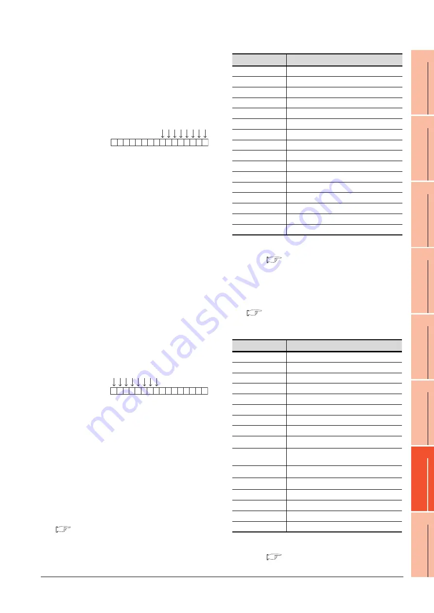
Write 1 to the bits of device SP122 that correspond to the
Forward rotation command (WS1) and Low speed
operation command (WS3).
In this example, device SP122 must store 000AH.
Convert 000AH to a decimal value (10), and then write 10
to device SP122.
• Setting the JOG operation command (WS8), Selection of
automatic restart after instantaneous power failure
command (WS9), Start self-holding selection command
(WS10), and Reset command (WS11)
When setting the above commands, write values to device
SP121 as necessary. As shown in the figure below, each
operation mode is assigned to a bit of device SP121. The
following shows an example of setting the Reset
command (WS11).
Write 1 to the bit of device SP121 that corresponds to the
Reset command (WS11). In this example, device SP121
must store 0800H. Convert 0800H to a decimal value
(2048), and then write 2048 to device SP121.When using
a WS device, [Alternate] of a bit switch cannot be used.
Use [Momentary], [Set], and [Reset] for bit switch actions.
When using a WS device, [Alternate] of a bit switch cannot
be used.
Use [Set], [Reset], and [Momentary] of a bit switch.
The following shows correspondences between virtual
inverter devices used in the GOT and data of the
inverter.
(1) Inverter status monitor
An example with FREQROL-A700 series is shown
below. For the setting items of other than the
FREQROL-A700 series, refer to the following manual.
User's Manual of the used inverter
(communication function (setting item and set
data))
*1
The description (function of input terminal) may be changed
by the parameter of the inverter side. Check the function of
the inverter used.
Inverter User's Manual (Application) Communication
operation and setting
(2) Run command
An example with FREQROL-A700 series is shown
below. For the setting items of other than the
FREQROL-A700 series, refer to the following manual.
User's Manual of the used inverter
(Communication function (Setting item and set
data))
*1
The data (function of input terminal) may be changed by the
parameter of the inverter side. Check the function of the
inverter used.
Inverter User's Manual (Application) Communication
operation and setting
Device SP122
b15
b7
b0
0 0 0 0 0 0 0 0 0 0 0 0 1 0 1 0
WS7: Output stop(MRS)
WS6: Second function selection(RT)
WS5: High speed operation command(RH)
WS4: Middle speed operation command(RM)
WS3: Low speed operation command(RL)
WS2: Reverse rotation command(STR)
WS1: Forward rotation command(STF)
WS0: Current input selection(AU)
Device SP121
b15
b7
b0
0 0 0 0 1 0 0 0 0 0 0 0 0 0 0 0
WS15: Not used
WS14: Not used
WS13: Not used
WS12: Not used
WS11: Reset (RES)
WS10: Selection of automatic restart after instantaneous power failure (CS)
WS9: Start self-holding selection (STOP)
WS8: JOG operation (JOG)
Device name
Description
*1
RS0
Inverter running (RUN)
RS1
Forward rotation (STF)
RS2
Reverse rotation (STR)
RS3
Up to frequency (SU)
RS4
Overload (OL)
RS5
Instantaneous power failure (IPF)
RS6
Frequency detection (FU)
RS7
Fault (ABC1)
RS8
ABC2
RS9
-
RS10
-
RS11
-
RS12
-
RS13
-
RS14
-
RS15
Fault occurrence
Device name
Description
*1
WS0
Current input selection (AU)
WS1
Forward rotation command (STF)
WS2
Reverse rotation command (STR)
WS3
Low speed operation command (RL)
WS4
Middle speed operation command (RM)
WS5
High speed operation command (RH)
WS6
Second function selection (RT)
WS7
Output stop (MRS)
WS8
*2
Jog operation (JOG)
WS9
*2
Selection of automatic restart after instantaneous
power failure (CS)
WS10
*2
Start self-holding (STOP)
WS11
*2
Reset (RES)
WS12
-
WS13
-
WS14
-
WS15
-
Содержание GT15
Страница 2: ......
Страница 34: ...A 32 ...
Страница 92: ......
Страница 110: ...2 18 2 DEVICE RANGE THAT CAN BE SET 2 9 MELSEC WS ...
Страница 134: ...3 24 3 ACCESS RANGE FOR MONITORING 3 7 Connection to the Head Module of CC Link IE Field Network System ...
Страница 186: ...5 10 5 BUS CONNECTION 5 2 System Configuration ...
Страница 218: ...5 42 5 BUS CONNECTION 5 4 Precautions ...
Страница 254: ...6 36 6 DIRECT CONNECTION TO CPU 6 6 Precautions ...
Страница 286: ...7 32 7 COMPUTER LINK CONNECTION 7 6 Precautions ...
Страница 350: ...8 64 8 ETHERNET CONNECTION 8 5 Precautions ...
Страница 368: ...9 18 9 MELSECNET H CONNECTION PLC TO PLC NETWORK 9 5 Precautions ...
Страница 420: ...11 26 11 CC Link IE CONTROLLER NETWORK CONNECTION 11 5 Precautions ...
Страница 440: ...12 20 12 CC Link IE FIELD NETWORK CONNECTION 12 5 Precautions ...
Страница 490: ...13 50 13 CC Link CONNECTION INTELLIGENT DEVICE STATION 13 5 Precautions ...
Страница 510: ......
Страница 564: ...15 54 15 INVERTER CONNECTION 15 7 Precautions ...
Страница 668: ......
Страница 712: ...21 12 21 MULTIPLE GT14 GT12 GT11 GT10 CONNECTION FUNCTION 21 5 Precautions ...
Страница 713: ...MULTI CHANNEL FUNCTION 22 MULTI CHANNEL FUNCTION 22 1 ...
Страница 714: ......
Страница 760: ...22 46 22 MULTI CHANNEL FUNCTION 22 5 Multi channel Function Check Sheet ...
Страница 761: ...FA TRANSPARENT FUNCTION 23 FA TRANSPARENT FUNCTION 23 1 ...
Страница 762: ......
Страница 860: ...REVISIONS 4 ...
Страница 863: ......


