1. PREPARATORY PROCEDURES FOR MONITORING
1.1 Setting the Communication Interface
1 - 3
1
P
R
EP
ARA
T
OR
Y
P
R
OCEDURES
FOR
MONIT
O
R
ING
2
D
E
VICE RA
NGE
T
H
A
T
CAN
B
E
SET
3
ACCESS
RA
N
G
E
F
O
R MONIT
O
R
ING
4
HOW T
O
MONIT
O
R
REDUNT
ANT
SYS
TEM
5
BUS CONNECTION
6
DIR
E
CT
CONNECTION T
O
CPU
7
COMP
UT
E
R
L
INK
CONNE
C
T
ION
8
E
T
HE
RN
E
T
CONN
E
C
T
ION
1.1 Setting the Communication Interface
Set the communication interface of GOT and the connected equipment.
When using the GOT at the first time, make sure to set the channel of communication interface and the communication
driver before writing to GOT.
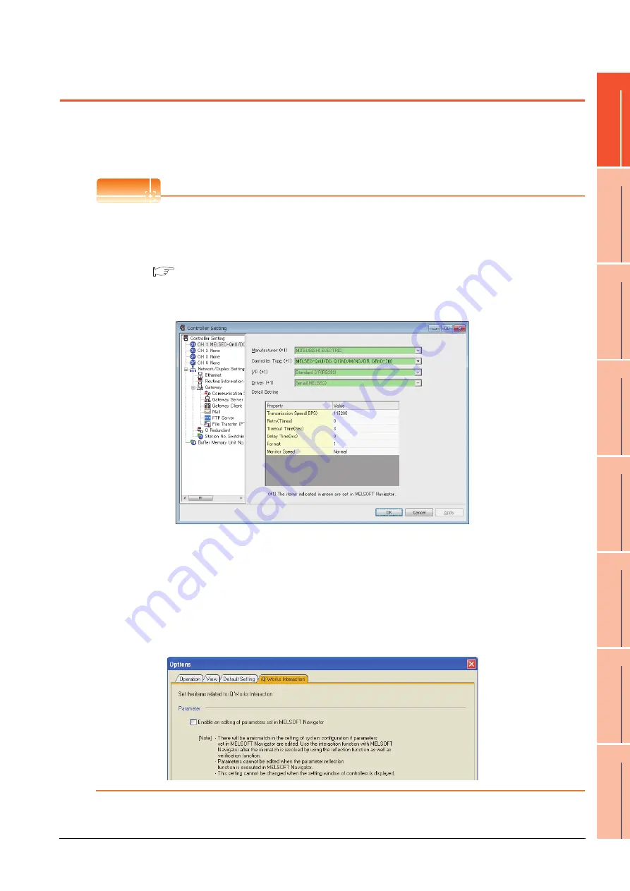
Set the communication interface of the GOT at [Controller Setting] and [I/F Communication Setting] in GT Designer3.
POINT
POINT
POINT
When using the parameter reflection function of MELSOFT Navigator.
The system configuration of MELSOFT Navigator can be reflected to the project of GT Designer3 using the
parameter function of MELSOFT Navigator.
For details of the parameter functions of MELSOFT Navigator, refer to the following.
Help of MELSOFT Navigator
(1) The color of the cells for the items which are reflected to GT Designer3 from MELSOFT Navigator changes to
green. Set items, which are displayed in green cells, from the MELSOFT Navigator. When changing in GT
Designer3, refer to the following (3).
(2) When setting the communication interface for the connection with the iQ Works untargeted equipment, set
[Set with GT Designer3] to the channel connected at [Input Detailed Configuration Information] in MELSOFT
Navigator and make the settings at [Controller Setting] in GT Designer3.
(3) To make the items reflected from MELSOFT Navigator editable on GT Designer3, select the [Option] menu
and put a check mark at [Enable an editing of parameters set in MELSOFT Navigator] in the [iQ Works
Interaction] tab.
However, when the items set in MELSOFT Navigator are edited in GT Designer3, the interaction function with
MELSOFT Navigator is unavailable due to a mismatch with the system configuration of MELSOFT Navigator.
Eliminate mismatches using the parameter verification function etc. before using the interaction function of
MELSOFT Navigator.
Содержание GT15
Страница 2: ......
Страница 34: ...A 32 ...
Страница 92: ......
Страница 110: ...2 18 2 DEVICE RANGE THAT CAN BE SET 2 9 MELSEC WS ...
Страница 134: ...3 24 3 ACCESS RANGE FOR MONITORING 3 7 Connection to the Head Module of CC Link IE Field Network System ...
Страница 186: ...5 10 5 BUS CONNECTION 5 2 System Configuration ...
Страница 218: ...5 42 5 BUS CONNECTION 5 4 Precautions ...
Страница 254: ...6 36 6 DIRECT CONNECTION TO CPU 6 6 Precautions ...
Страница 286: ...7 32 7 COMPUTER LINK CONNECTION 7 6 Precautions ...
Страница 350: ...8 64 8 ETHERNET CONNECTION 8 5 Precautions ...
Страница 368: ...9 18 9 MELSECNET H CONNECTION PLC TO PLC NETWORK 9 5 Precautions ...
Страница 420: ...11 26 11 CC Link IE CONTROLLER NETWORK CONNECTION 11 5 Precautions ...
Страница 440: ...12 20 12 CC Link IE FIELD NETWORK CONNECTION 12 5 Precautions ...
Страница 490: ...13 50 13 CC Link CONNECTION INTELLIGENT DEVICE STATION 13 5 Precautions ...
Страница 510: ......
Страница 564: ...15 54 15 INVERTER CONNECTION 15 7 Precautions ...
Страница 668: ......
Страница 712: ...21 12 21 MULTIPLE GT14 GT12 GT11 GT10 CONNECTION FUNCTION 21 5 Precautions ...
Страница 713: ...MULTI CHANNEL FUNCTION 22 MULTI CHANNEL FUNCTION 22 1 ...
Страница 714: ......
Страница 760: ...22 46 22 MULTI CHANNEL FUNCTION 22 5 Multi channel Function Check Sheet ...
Страница 761: ...FA TRANSPARENT FUNCTION 23 FA TRANSPARENT FUNCTION 23 1 ...
Страница 762: ......
Страница 860: ...REVISIONS 4 ...
Страница 863: ......


