5. BUS CONNECTION
5.4 Precautions
5 - 37
1
P
R
EP
ARA
T
OR
Y
P
R
OCEDURES
FOR
MONIT
O
R
ING
2
D
E
VICE RA
NGE
T
H
A
T
CAN
B
E
SET
3
ACCESS
RA
N
G
E
F
O
R MONIT
O
R
ING
4
HOW T
O
MONIT
O
R
REDUNT
ANT
SYS
TEM
5
BUS CONNECTION
6
DIR
E
CT
CONNECTION T
O
CPU
7
COMP
UT
E
R
L
INK
CONNE
C
T
ION
8
E
T
HE
RN
E
T
CONN
E
C
T
ION
5.4.3
Powering OFF the GOT,
reapplying the power (OFF to
ON)
(1) Precautions for reapplying the power to the GOT
(OFF to ON)
Do not power-cycle the GOT (OFF to ON) while the
PLC is ON.
Before doing so, be sure to turn off the PLC first.
HINT
HINT
HINT
Operations causing automatic reboot of the GOT1000
Series
Since the GOT1000 Series is automatically rebooted
in the following cases, the power does not need to be
reapplied to the GOT (OFF to ON).
• When an OS is written from GT Designer3 or a CF
card
• When utility settings have been changed
(2) When turning OFF the GOT before display of the
user creation screen
When the GOT is turned OFF before the user creation
screen is displayed on the GOT, subsequent
communications may be no longer possible.
In such a case, reapply the power to the PLC CPU and
GOT.
(3) Precautions for connection of 3 GOTs or more (when
connecting QCPU (Q mode))
5.4.10 (1)Restrictions in overall cable length to
No. of GOTs
5.4.4
Reset switch on GOT
When bus connection is used, the reset switch on the GOT
does not function.
5.4.5
Powering OFF or resetting the
PLC
(1) When turning OFF or resetting the PLC during
monitoring
When turning OFF or resetting the PLC during
monitoring, the system alarm (No.402: timeout error) is
generated.
When the PLC CPU is restored, the GOT automatically
resumes monitoring.
Use System Information to reset the alarm.
For the System Information, refer to the following
manual:
GT Designer3 Version Screen Design
Manual
(2) When turning OFF or resetting the PLC CPU before
display of the user creation screen
When the PLC CPU is turned OFF or reset before the
user creation screen is displayed on the GOT,
subsequent communications may be no longer
possible.
In such a case, reapply the power to the PLC CPU and
GOT.
(3) Precautions for connection of 3 GOTs or more (when
connecting QCPU (Q mode))
5.4.10 (1)Restrictions in overall cable length to
No. of GOTs
5.4.6
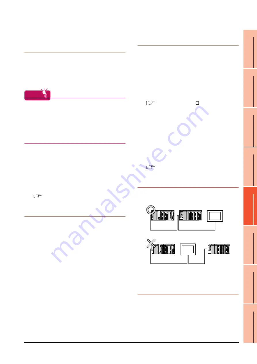
Position of the GOT
Always connect the GOT to the last base unit.
Connecting a GOT between base units is not allowed.
5.4.7
When the GOT is bus-
connected to a PLC CPU
without the communication
driver written
When the GOT is bus-connected to a PLC CPU without the
standard monitor OS and the communication driver for the
bus connection being written onto the GOT, the PLC CPU
is reset. (GX Developer cannot communicate with the PLC
CPU)
In this case, disconnecting the bus connection cable from
the GOT will cancel the reset status of the PLC CPU.
Содержание GT15
Страница 2: ......
Страница 34: ...A 32 ...
Страница 92: ......
Страница 110: ...2 18 2 DEVICE RANGE THAT CAN BE SET 2 9 MELSEC WS ...
Страница 134: ...3 24 3 ACCESS RANGE FOR MONITORING 3 7 Connection to the Head Module of CC Link IE Field Network System ...
Страница 186: ...5 10 5 BUS CONNECTION 5 2 System Configuration ...
Страница 218: ...5 42 5 BUS CONNECTION 5 4 Precautions ...
Страница 254: ...6 36 6 DIRECT CONNECTION TO CPU 6 6 Precautions ...
Страница 286: ...7 32 7 COMPUTER LINK CONNECTION 7 6 Precautions ...
Страница 350: ...8 64 8 ETHERNET CONNECTION 8 5 Precautions ...
Страница 368: ...9 18 9 MELSECNET H CONNECTION PLC TO PLC NETWORK 9 5 Precautions ...
Страница 420: ...11 26 11 CC Link IE CONTROLLER NETWORK CONNECTION 11 5 Precautions ...
Страница 440: ...12 20 12 CC Link IE FIELD NETWORK CONNECTION 12 5 Precautions ...
Страница 490: ...13 50 13 CC Link CONNECTION INTELLIGENT DEVICE STATION 13 5 Precautions ...
Страница 510: ......
Страница 564: ...15 54 15 INVERTER CONNECTION 15 7 Precautions ...
Страница 668: ......
Страница 712: ...21 12 21 MULTIPLE GT14 GT12 GT11 GT10 CONNECTION FUNCTION 21 5 Precautions ...
Страница 713: ...MULTI CHANNEL FUNCTION 22 MULTI CHANNEL FUNCTION 22 1 ...
Страница 714: ......
Страница 760: ...22 46 22 MULTI CHANNEL FUNCTION 22 5 Multi channel Function Check Sheet ...
Страница 761: ...FA TRANSPARENT FUNCTION 23 FA TRANSPARENT FUNCTION 23 1 ...
Страница 762: ......
Страница 860: ...REVISIONS 4 ...
Страница 863: ......


