23 - 62
23. FA TRANSPARENT FUNCTION
23.6 Personal Computer Side Setting
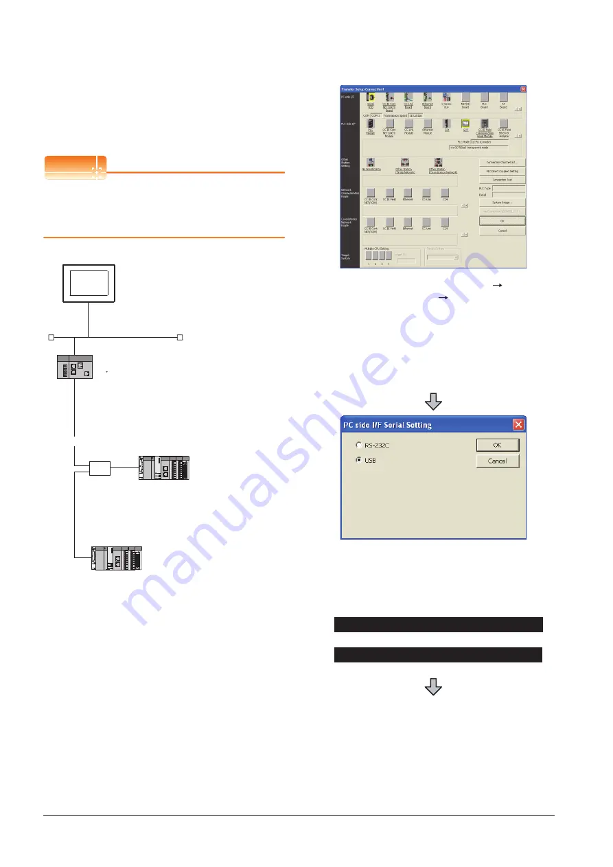
(4) Connecting the GOT and Ethernet adapter (NZ2GF-
ETB) in Ethernet connection, and connecting it to a
PLC in the CC-Link IE Field Network.
This section describes the settings of the GX Works2 in
the following case of system configuration.
POINT
POINT
POINT
Version of GX Works2
GX Works2 Version 1.34L or later is required to
execute the FA transparent function with using
Ethernet adapter (NZ2GF-ETB).
Network No.
:3
PC No.
:1
IP address
:192.168.3.18
Port No.
:5001
Communication
format
:UDP (fixed)
Ethernet
CC-Link IE Field Network
HUB
<Ethernet adapter module>
(Use default value for settings other than the following.)
Ethernet setting
IP address
CC-Link IE Field Network setting
Network No.
Station No.
:192.168.3.30
:1
:1
<CC-Link IE Field Network Master/Local module>
(Use default value for settings other than the following.)
Network Type
Network No.
PC No.
Total Stations
: CC IE Field (Master station)
: 1
: 0
: 2
<CC-Link IE Field Network Master/Local module>
(Use default value for settings other than the following.)
Network Type
Network No.
PC No.
: CC IE Field (Local station)
: 1
: 2
<GOT>
(Use default value for settings other than the following.)
1.
Click the Connection Destination view
[Connection Destination]
[(Connection target data
name)] in the Navigation window of GX Works2.
2.
The [Transfer Setup Connection1] is displayed.
3.
Set the [Transfer Setup Connection1].
PC side I/F
: Serial USB
PLC side I/F
: GOT
4.
Double-click [Serial USB] of the PC side I/F to display
[PC side I/F Serial Setting].
5.
Check-mark either of the following in [PC side I/F
Serial Setting].
Mark the [RS-232C] checkbox.
Mark the [USB] checkbox.
When connecting the GOT and PC with serial
When connecting the GOT and PC with USB
Содержание GT15
Страница 2: ......
Страница 34: ...A 32 ...
Страница 92: ......
Страница 110: ...2 18 2 DEVICE RANGE THAT CAN BE SET 2 9 MELSEC WS ...
Страница 134: ...3 24 3 ACCESS RANGE FOR MONITORING 3 7 Connection to the Head Module of CC Link IE Field Network System ...
Страница 186: ...5 10 5 BUS CONNECTION 5 2 System Configuration ...
Страница 218: ...5 42 5 BUS CONNECTION 5 4 Precautions ...
Страница 254: ...6 36 6 DIRECT CONNECTION TO CPU 6 6 Precautions ...
Страница 286: ...7 32 7 COMPUTER LINK CONNECTION 7 6 Precautions ...
Страница 350: ...8 64 8 ETHERNET CONNECTION 8 5 Precautions ...
Страница 368: ...9 18 9 MELSECNET H CONNECTION PLC TO PLC NETWORK 9 5 Precautions ...
Страница 420: ...11 26 11 CC Link IE CONTROLLER NETWORK CONNECTION 11 5 Precautions ...
Страница 440: ...12 20 12 CC Link IE FIELD NETWORK CONNECTION 12 5 Precautions ...
Страница 490: ...13 50 13 CC Link CONNECTION INTELLIGENT DEVICE STATION 13 5 Precautions ...
Страница 510: ......
Страница 564: ...15 54 15 INVERTER CONNECTION 15 7 Precautions ...
Страница 668: ......
Страница 712: ...21 12 21 MULTIPLE GT14 GT12 GT11 GT10 CONNECTION FUNCTION 21 5 Precautions ...
Страница 713: ...MULTI CHANNEL FUNCTION 22 MULTI CHANNEL FUNCTION 22 1 ...
Страница 714: ......
Страница 760: ...22 46 22 MULTI CHANNEL FUNCTION 22 5 Multi channel Function Check Sheet ...
Страница 761: ...FA TRANSPARENT FUNCTION 23 FA TRANSPARENT FUNCTION 23 1 ...
Страница 762: ......
Страница 860: ...REVISIONS 4 ...
Страница 863: ......


