DIP Switches
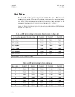
Before operating Access-T, you must set the DIP switches for the hardware configu-
ration, node address, and desired software operation mode. All possible configura-
tion options are defined in Tables 3-A and 3-B and in the following sections.
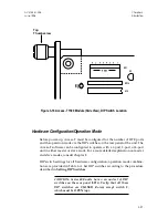
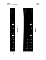
The DIP switches for the Access-T 100, 200, and 400 units are accessible through
holes in the rear panel. Figure 3-1 shows the location of the switches. DIP
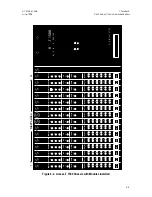
switches for the Access-T 1500 module are accessible on the side of the card.
(You need to only partially remove the Access-T 1500 plug-in module to set the
DIP switches.) Figure 3-18 shows the location of the switches.
Setting DIP Switches
Use the following procedure to configure DIP switches:
1.
If you are configuring a Series 100, 200, or 400 unit, verify that the
unit is not powered up.
2.
Locate the 8 position DIP switches, shown in Figure 3-1 (Series 100, 200,
and 400) or Figure 3-18 (Series 1500). If setting DIP switches on an
Access-T 1500 module, partially remove the module from the chassis as
described under Removing and Inserting Access-T 1500 Modules.
3.
Using a small screwdriver or other tool, set DIP switches 1 through
8 for the desired configuration as indicated in Table 3-A or Table 3-B.
Open
indicates the up position; closed indicates the down position.
WARNING: Do not use a graphite (lead) pencil
to operate the switches. Graphite particles may
short the switches, damaging the unit.
Verify your switch settings before powering up
the unit. Invalid switch settings could cause
your unit to reset its default settings, or produce
other problems.
4.
If you have removed the Access-T 1500 module from the chassis,
re-insert it in the chassis as described under Removing and Inserting
Access-T 1500 Modules
. Power up the unit to intiate the new DIP
switch settings.
Chapter 3
ACST-0351-005
Installation
June 1996
3-26

