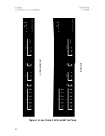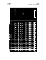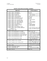
Table 4-A. Front-Panel Status Indicators
GROUP
INDICATOR
COLOR
CONDITION
SYSTEM
STATUS
Red
Amber
Green
Self-test failure, or NIM or Main processor operating in
boot mode
DCD active (modem connection and terminal session
established)
Normal operation
NETWORK
LINE
LOOP
TEST
Red
Amber
Green
Amber
Amber
Loss of sync or Loss of Signal on input from the T1 line
(or NIM failure)
Yellow Signal being received from the T1 line
Normal signal present from T1 line
Either LS Line, LS DTE, DS Line, or DS DTE
loopbacks are active
QRSS test is active
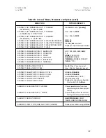
DTE PORT
1, 2, 3, and 4
MAP
LOOP
XMT
RCV
RTS
CTS
Green
Amber
Green
Green
Green
Green
Port is mapped onto the network
CS DTE or CS Line loopback is active
Data signal is being transmitted to Access-T
Data is being transmitted from Access-T
RTS is being received
Normal data transmission
AUX
D&I
Red
Amber
Green
Off
Loss of Signal or Loss of Sync on Aux T1 DTE
Yellow Signal being received from the T1 line
Normal Operation
Auxiliary T1 DTE Port is not assigned to any DS0s
CRAFT *
PORT
VT100
TV925
Green
Green
On indicates VT100 type terminal emulations selected;
Blinks when auto baud function is active
On indicates TV 925 type terminal selected;
Blinks when auto baud function is active
POWER
SUPPLY **
(not labelled)
PS1, PS2
Green
Red
Off
On indicates normal operation
On indicates one or more supply voltages out of
range, no input to power supply, or other power failure
Off indicates that no power supply is loaded into the
slot, failure of the monitor card, or failure of the LED
* For the Access-T 1500, the Craft Port and its related LEDs are located on the rear panel.
** The PS1 and PS2 LEDs are applicable only for the Access-T 1500.
Chapter 4
ACST-0351-005
Front-Panel Controls and Indicators
June 1996
4-4


