background image

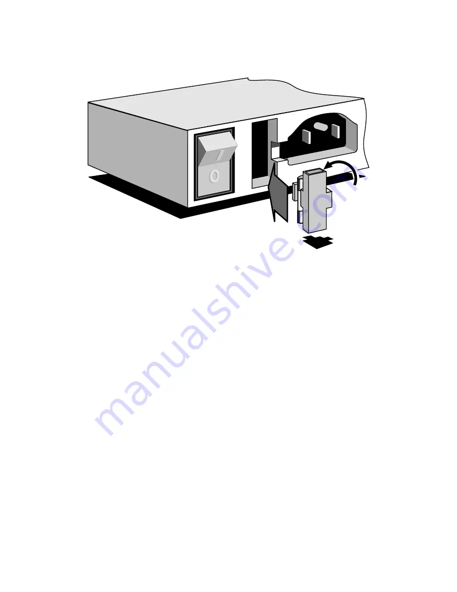
Figure 9-1. Partial View of Access-T Series 100, 200, and 400 Rear Panel

with Fuse Assembly Removed (AC Power)

6.

Remove the spare fuse and insert it where you removed the blown
fuse in step 3.

7.

Replace the spare fuse box in the fuse assembly.

8.

Re-install the fuse assembly into Access-T 200 or 400 rear panel.

9.

Re-insert the power cord and restore power to the unit.

Note:

If no spare fuse is inside the fuse assembly or if

you wish to order extra fuses, call Larscom and ask for
part number 250-120-75 (1-port or 2-port) or 250-120-
95 (4-port).

Access-T Series 100, 200, and 400 Units, DC Power

Access-T 100, 200, and 400 units powered by a dc source do not have a spare
fuse included within the unit. If the fuse blows, call Larscom and ask for part
number 250-110-90 (2-port) or 250-110-50 (4-port).

C

B

D

A

Chapter 9

ACST-0351-005

Maintenance

June 1996

9-2

Содержание ACST-1500B Series

Страница 1: ...ss underutilized and idle equipment along with credit for buybacks and trade ins Custom engineering so your equipment works exactly as you specify Critical and expedited services Leasing Rentals Demos In stock Ready to ship TAR certified secure asset solutions Expert team I Trust guarantee I 100 satisfaction All trademarks brand names and brands appearing herein are the property of their respectiv...

Страница 2: ...Access T 100 200 400 1500 Multi port DSU CSU System Installation and Operation Manual ACST 0351 005 June 1996 ...

Страница 3: ... subject to change without notice Access T is a trademark of Larscom Incorporated Larscom Incorporated 4600 Patrick Henry Drive Santa Clara CA 95054 Telephone 408 988 6600 Customer Service 408 988 6627 Fax 408 986 8690 World Wide Web http www larscom com Copyright 1996 Printed in U S A ...

Страница 4: ...Network Interface 3 If Access T appears to be malfunctioning disconnect it from the telephone line until it is determined whether the Access T or the line is the source of the trouble If Access T needs repair do not reconnect it to the line until the repair has been completed 4 Access T has been designed to prevent disruption of the T1 FT1 network If Orion is not meeting performance requirements t...

Страница 5: ...acility designated by the supplier Any repairs or alterations made by the user to this equipment or equipment malfunctions may give the telecommunications company cause to request the user to disconnect the equipment Users should ensure for their own protection that the electrical ground connections of the power utility telephone lines and internal metallic water pipe system if present are connect...

Страница 6: ...s and can radiate radio frequency energy and if not installed in accordance with the instructions in this manual may cause harmful interference to radio communications Op eration of this equipment in a residential area is likely to cause harmful interference in which case the user will be required to correct the interference at his own expense Warning Changes or modifications to this unit not expr...

Страница 7: ...s200 integral SNMP one supervisory connection serves all modules This manual describes the functions and capabilities of the Larscom Access T Series 100 200 400 and 1500 products Although identical in software these two versions of the product have significant physical differences which are noted throughout this manual as appropriate When the term Access T is used in this manual it refers to the A...

Страница 8: ... It describes each menu path and its associated options and parameters Chapter 6 Configuration Procedures This chapter provides proce dures for configuring Access T through the Terminal Interface Chapter 7 Alarms Reports and Tests This chapter describes the Access T displays and commands used to monitor the performance and status of the communication links and the procedures for performing all dia...

Страница 9: ...gital communication system in North America A T1 facility provides full duplex transmission at 1 544 megabits per second Mbps Bandwidth is divided into 8 kbps of overhead and 1 536 Mbps of user information For digitized voice applications the information bandwidth typically consists of 24 multiplexed 64 kbps channels For the transmission of data a T1 facility may be channelized as for voice or it ...

Страница 10: ...density assurance Keep Alive and Yellow Signal Loopback to the line controlled from the network T1 Signal Characteristics The T1 signal is a bipolar pulse train Data is encoded using pulse code modu lation PCM and time division multiplexing TDM In other words the signal is divided into time slots of 648 nanoseconds each 1 544 000 time slots per second with data encoded by the presence or absence o...

Страница 11: ...e last repeater to be 3000 feet Access T CSUs accurately regenerate a 27 dB signal equivalent to the attenu ation over 5000 feet of cable Figure 1 2 shows one end of a typical T1 link T1 may also be transmitted via satellites digital microwave radios fiber optic systems and coaxial cable modems In the carrier networks T1 signals may be multiplexed into even higher speed signals e g T3 Figure 1 1 A...

Страница 12: ...on T1 facilities can handle up to 80 consecutive ZEROS Pulse density requirements may be enforced by either theDTE or the DSU CSU depending on the particular application Pulse density may be guaranteed in various ways A particular bit position generally bit 7 or 8 of each data byte may be reserved for the transmission of a pulse A pulse may be stuffed in the data stream i e a ZERO may be overwritt...

Страница 13: ...ng two bipolar violations BPVs as illustrated in Figure 1 3 There are two requirements for the use of B8ZS The CSUs or DTE at each end of the T1 link must be able to encode and decode B8ZS Network equipment through which the signal passes must be trans parent to B8ZS in other words must not correct the BPVs in the B8ZS code The latter requirement prevents the current implementation of B8ZS in many...

Страница 14: ... illustrates the D4 framing format All 12 overhead F bits in each Superframe are used for frame synchronization As more T1 networks were deployed a primary deficiency in D4 the inability to monitor live data became significant To monitor performance on a D4 circuit live traffic must be halted and test signals transmitted on the line When improvements in synchronizing circuits reduced the requireme...

Страница 15: ...ps channel called the Facility Data Link FDL for diagnostic control and transmission of performance statistics Table 1 A shows bit by bit use of the 24 overhead bits and the robbed signaling bits in each ESF Currently there are two standards for ESF The first was developed by AT T and is described in AT T Publication 54016 More recently the Exchange Carriers Standards Association developed the ANS...

Страница 16: ...Bit 3 Channel 1 2 24 Frame 1 2 3 4 5 6 7 8 9 10 11 12 1 0 0 0 1 1 0 1 1 1 0 0 V V V V V V V V V V V V V V V V V V V V V V V V V V V V V V V V V V V V V V V V V V V V V V V V V V V V V V V V V V V V V V V V V V V V V V V V V V V V V V V V V V V V V V V V V A V V V V V B A Signaling Frame B Signaling Frame 8 Bit Voice 8 Bit Voice 7 Bit Voice 7 Bit Voice F Framing overhead bit V Bit used for voice co...

Страница 17: ... Bits 1 7 Bits 1 8 Bits 1 8 Bits 1 8 Bits 1 8 Bits 1 8 Bits 1 7 Bits 1 8 Bits 1 8 Bits 1 8 Bits 1 8 Bits 1 8 Bits 1 7 Bits 1 8 Bits 1 8 Bits 1 8 Bits 1 8 Bits 1 8 Bits 1 7 Bit 8 Bit 8 Bit 8 Bit 8 A A A A A B A B A B C D Notes Fe ESF Framing Bits 001011 FDL 4 kbps Facility Data Link message bits m CRC CRC 6 Block Check check bits C1 C6 Option T Transparent bit 8 for traffic Option 2 2 State Signali...

Страница 18: ... are not SES Loss of Frame Count LOFC The number of times Loss of Frame is declared Loss of Frame is declared when a device loses sync on the framing pattern for approximately 2 5 seconds Loss of Frame is cleared when a device maintains sync for about 15 milliseconds Controlled Slips CS Monitored and reported by devices which perform controlled timing slips optional ES BES SES and UAS counts are t...

Страница 19: ...403 defines two loopbacks Line Loopback and Payload Loopback which are the same as the loopbacks defined in AT T Publication 54016 However under ANSI T1 403 both loopbacks are controlled via the data link Channelization and Robbed Bit Signaling As shown in Figure 1 4 the 192 information bits in each frame may be divided into twenty four 8 bit channels for the transmission of digitized voice This c...

Страница 20: ... N1 G1 1 1 CRC Error Event G2 1 2 to 5 CRC Error Events G3 1 6 to 10 CRC Error Events G4 1 11 to 100 CRC Error Events G5 1 101 to 319 CRC Error Events G6 1 320 or more CRC Error Events FE 1 At least 1 Framing Bit Error no SE SE 1 At least 1 Severely Errored Framing Event LV 1 At least 1 Line Code Violation BPV SL 1 At least 1slip event LB 1 Payload loopback activated U1 U2 Usage under study R Rese...

Страница 21: ...ng is performed by a DACS Digital Access Cross Connect Switch at each network office FT1 is used with DTEs operating at less than the full T1 rate Thus a DSU is required to convert the lower rate signals to the T1 rate and format A DSU may serve a single DTE or it may multiplex the signals from two or more DTEs In addition a DSU may provide drop and insert capability for T1 DTEs This feature allow...

Страница 22: ...tandard protocol It takes up few system resources in the managed device It operates in multi vendor environment This section contains a brief overview of SNMP along with a short description of the TCP IP protocol suite and IP addressing modes A more detailed discus sion of these topics can be found in many TCP IP and SNMP reference books including Internetworking with TCP IP by Douglas E Comer Fig...

Страница 23: ...d base of equipment that does not support SNMP Using Integral SNMP where the managed device already speaks SNMP over its management interface This more efficient method is used by Access T In Figure 1 7 SNMP operates over Access T s RS232 Supervisory Ports configured for the serial link interface protocol SLIP or point to point protocol PPP to carry the packetized SNMP messages SNMP Manager Termin...

Страница 24: ...resentation Most SNMP management operations are achieved through GET and SET commands The GET SET structure is a simple request reply protocol typi cally the SNMP manager sends a request and the managed device i e the Access T sends back a reply These commands operate on variables that exist in network nodes Variables are the information such as T1 performance registers or framing format that is q...

Страница 25: ...pecify and describe Internet protocols An Application Specific MIB which contains the objects or vari ables for such applications as different types of network interfaces For instance there are Application Specific MIBs defined by differ ent RFCs for both DS1 and DS3 network interfaces Access T sup ports the DS1 application MIB specified by RFC 1406 An Enterprise Specific MIB which is defined by t...

Страница 26: ...rovides a connectionless packet delivery system Each layer of the protocol is responsible for different communication functions Figure 1 8 provides an example of TCP IP protocol layers for an SNMP application Figure 1 8 TCP IP Protocol Layers for an SNMP Application RS232 Bit Transmission SNMP Manager Access T SNMP Managed Device User Datagram Protocol UDP Internet Protocol IP SLIP or PPP SLIP or ...

Страница 27: ... IP applica tions such as SNMP Other TCP IP applications include Telnet File Transfer Protocol FTP or Simple Mail Transfer Protocol SMTP Transport Layer provides a flow of data between two hosts for the application layer above SNMP uses UDP a simple non reliable service as a transport layer protocol Other TCP IP applications use Transmission Control Protocol TCP as the transport layer Network Laye...

Страница 28: ...ess can be imagined to have two parts a netid and hostid Per their names netid identifies a network while hostid identifies a host on that network Figure 1 9 shows a breakdown of the five classes of IP addresses Classes can be determined from the three high order bits with two bits being sufficient to distinguish the three primary forms Classes A B and C These classes differ in the number of hosts...

Страница 29: ...sing the subnetid and the hostid do not have to be separated on byte boundaries Subnet Mask When subnetting is used hosts on the network need to be able to determine which IP address bits are used for the subnetid and which bits are used for the hostid The host will already have determined the class of the address from the netid field The subnet mask distinguishes the subnetid bits from the hostid...

Страница 30: ...ts Each decimal number gives the value of one octet i e byte of the IP address For example the 32 bit 4 byte binary internet address 10000000 00001010 00000010 00011110 is written in dotted decimal notation as 128 10 2 30 Each decimal number can range from 0 to 255 which corresponds to the range of one octet or byte As another example the IP address subnet mask shown in Figure 1 10 is written as 2...

Страница 31: ... address es A match indicates that the IP datagram can be sent directly If no match is made the sender passes the IP datagram to a gateway The IP datagram will continue from gateway to gateway until it reaches a gateway that can deliver the IP datagram directly Table Driven IP Routing Each host or gateway uses a table driven routing algorithm to determine where an IP datagram should be sent The IP...

Страница 32: ...ork 20 0 0 0 Network 30 0 0 0 Network 40 0 0 0 F G H 20 0 0 5 10 0 0 5 30 0 0 7 20 0 0 6 40 0 0 7 30 0 0 6 To reach hosts on network Route to this address 20 0 0 0 Deliver Directly 30 0 0 0 Deliver Directly 10 0 0 0 20 0 0 5 40 0 0 0 30 0 0 7 Chapter 1 ACST 0351 005 Introduction June 1996 1 26 ...

Страница 33: ...ended that an SNMP manager not make an other request until a response is received or a timeout occurs Access T does not support fragmentation of IP packets on either transmit or receive On the SNMP manager the timeout for requests depends on the following Tranmission delays between the manager and Access T Whether the request is for the master Access T or a slave on the chain Whether the request i...

Страница 34: ...ork needs Access T also includes advanced monitoring and alarm functions built in diagnostics and downloadable software upgrades Equipment Architecture The Access T Series 100 200 400 and 1500 differ in physical design These differences are highlighted in the following lists and documented in greater detail in the following sections The Access T Series 100 200 and 400 provide 1 2 or 4 DTE ports Su...

Страница 35: ...s T features downloadable software New software can be transmitted to the Access T from a local or remote PC Software downloads are performed without removing or replacing any hardware and with a minimal disruption of service The rear panel is described in more detail in Chapter 3 For more information about the front panel refer to Chapter 4 Access T Applications Access T combines unique features ...

Страница 36: ...management system Access T can be used in point to point and multipoint applications In point to point applications a single T1 or FT1 link connects equipment at two locations In multipoint applications an FT1 network routes communication channels groups of DS0s to three or more locations through DCS nodes Figure 2 1 shows a typical multipoint application Figure 2 1 Typical Access T Application T1...

Страница 37: ... 1500 chassis must be installed in slot 15 See Chapter 3 for more information To facilitate management of the chained units or nodes a master Access T supports additional features and commands not available in slave mode The operator can specify the addresses of the slaves to be polled by the master Access T and which slaves will cause alarm dialout by the master if they do not respond to polls Th...

Страница 38: ...typically issued from a Network Management System NMS Serial Line Interface Protocol SLIP is an Internet protocol used to run IP over serial lines such as RS232 cables interconnecting two systems Point to Point Protocol PPP is an Internet protocol used to provide router to routerandhost to networkconnectionsoverbothsynchronous and asynchronous circuits Each Access T chassis is equipped with three ...

Страница 39: ...perform diagnostics etc Performance and alarm displays fit within one 21 line screen always displayed below the Title Bar and Main Menu Line The Terminal Interface described in detail in Chapter 5 can be accessed via the Supervisory and Craft Ports Automatic dialout to report alarms is supported only via the Supervisory Port TABS Interface The modified TABS Interface allows an NMS to control confi...

Страница 40: ...e PPP interface which is described in RFC 1331 is responsible for encapsulating SNMP i e IP datagrams In other words PPP defines a sequence of characters that frame SNMP datagrams on an RS232 serial point to point line Besides the encapsulation scheme PPP also provides a Link Control Protocol LCP for establishing configuring and testing the data link connection and a family of Network Control Prot...

Страница 41: ...ctions to a VT100 or TV 925 terminal Also the Craft Port does not require a password enabling you to perform first time configurations and troubleshooting easily Communication parameters are fixed at 8 data bits 1 stop bit and no parity A pushbutton accessible through the front panel rear panel on the Access T 1500 chassis lets you select the terminal type and initiate automatic baud rate detectio...

Страница 42: ... More detailed applications and Chain Port connections are illustrated in Chapters 3 and 8 Note The Chain Port does not support modem connections The Chain Port can also be used to connect an NMS directly to a master Access T or to a chain of slave Access Ts In the latter case the NMS must poll the slaves there will be no master Access T and no alarm dialout For these unusual applications aLarscom...

Страница 43: ...400 RS485 2 Wire Facilities Communicating Using TABS RS232 MASTER SLAVE SLAVE TERMINAL OR NMS RS485 2 Wire Facilities Communicating Using TABS RS232 Access T 1500 Access T 1500 Fully loaded with 15 modules Slot 15 MASTER slots 1 14 SLAVES Fully loaded with 15 modules Slots 1 15 SLAVES TERMINAL OR NMS Access T Series 100 200 or 400 Access T Series 100 200 or 400 RS485 2 Wire Facilities Communicatin...

Страница 44: ...e DB25 connector supporting the EIA 530 standard Larscomoffersadapter cablestoconverttoDC37 RS449 orMS34 V 35 connectors The pulse density required for T1 transmissions can be assured in several ways Transmitting data at a rate of Nx56 The least significant bit will always be a ONE Using B8ZS line coding Inverting HDLC formatted data Mapping data transmitted at a rate of Nx64 into alternate DS0s w...

Страница 45: ...he External Clock is inactive Transmit Data Transmit Clock External Clock Receive Clock Receive Data Phase Locked Loop required DTE wiring Pin 14 Pin 3 Pin 17 Pin 11 Pin 15 1 2 3 4 5 6 7 8 9 10 11 12 13 14 15 16 17 18 19 20 2122 23 24 T1 DTE Aux Drop and Insert T1 Line DTE 2 DTE 4 DTE 1 DTE 3 Data in DS0s 1 7 Data in DS0s 1 22 Network Interface 2 DS0s 128 kbps 4 DS0s 256 kbps 6 DS0s 384 kbps 3 DS0...

Страница 46: ...rcing bit 7 always to be a ONE toward the network only Alarm Indication Signal Generation of AIS to the line or Aux port when LOS or LOF occurs at the auxiliary port or line At least one DS0 must be assigned to the aux port for AIS to be generated Yellow transcoding Whether Yellow Signal is transcoded from a D4 auxiliary port to an ESF line or vice versa At least one DS0 must be assigned to the au...

Страница 47: ... disabled on a per bundle basis The line physical interface is as follows Access T 1 Port 2 Port and 4 Port units employ a female DA15 con nector An adapter is available to convert to an RJ48 jack Access T 1500 units employ two 50 pin female RJ48H connectors Each connector provides network access for specific Access T modules slot positions Larscom provides a separate RJ48C connector for each T1 l...

Страница 48: ...ecutive DS0s should not be mapped to that DTE port This precaution reduces the possi bility of excessive ZERO transmissions A DS0 bundling arrangement is called a map Access T allows you to create two different DS0 maps Switching between the two maps is performed on command or automatically In point to point applications the currently active map can be transmitted via the ESF data link to the far ...

Страница 49: ...r the auxiliary T1 DTE interface There is no telco BPV register per AT T Publication 54016 Separate user and telco registers for theline interface allow the user and the telco to clear registers without affecting each other Note Access T and other DSU CSUs do not perform control led slips Therefore Access T does not count Controlled Slip Seconds CSS Access T can display CSS register contents recei...

Страница 50: ...rvisory Port in three different ways Terminal Interface Mode Access T sends a one line ALERT banner identifying the Access T to an ASCII terminal The operator must then request an alarm history to identify the particular alarm TABS Unsolicited Mode Access T sends a complete alarm listing report in a modified TABS format to a network management system NMS The NMS must be programmed to interpret the...

Страница 51: ...s after 10 consecutive seconds which are not SES Loss of Signal SIGNAL LOSS Access T declares Loss of Signal if it receives 175 75 consecutive ZEROS A Loss of Signal alarm ends when a single ONE is detected Errored Seconds ES An ES alarm occurs when the user specified ES threshold is exceeded The threshold is a user specified number of Errored Seconds 1 to 399 over a user specified period of 1 to ...

Страница 52: ...ock in this case Internal Communication Failure INT COMM LOSS Access T cannot communicate between the lower and upper boards 4 port unit only Loss of Network Interface Module NIM LOSS A or B NIM LOSS A indicates that the NIM software is not responding NIM LOSS B refers to NIM loss on the upper board 4 port unit only DTE Alarms The DTE alarms PORT n LOSS indicate that Access T has lost the Request ...

Страница 53: ...d toward the DTE All Access T loopbacks are bridged which means that the normal signal path is not broken Therefore when a CS DTE loopback is active the signal from the DTE continues toward the far end Access T as well as being looped back toward the local DTE Naturally the signal path toward the local DTE is broken at the point where the looped signal is sent back to the DTE This prevents the sig...

Страница 54: ...face Local Access T Far End Access T 1 1 9 3 7 5 8 2 4 6 1 2 1 2 1 2 1 2 9 9 9 9 CS DTE Remote CS Line DS DTE Remote LS Line LS DTE Remote DS Line CS Line DS Line LS Line T1 Line T1 Line Interface 3 5 4 6 T1 Line Interface 8 7 Note Some Access T units are not equipped with an Aux port ACST 0351 005 Chapter 2 June 1996 Access T Functional Overview 2 21 ...

Страница 55: ...e mapped time slots CS Line loopbacks provide end to end testing which includes the line side functions of the Access T When a CS Line loopback is in effect the receive DTE data and clock replace the transmit DTE data and clock When the loopback is released the transmit clock switches back to its original source CS Line loopbacks can be activated either locally or remotely Line Loopbacks Various l...

Страница 56: ...uishing a Access T failure from a line failure During LS DTE loopbacks any data from the line is ignored by Access T Note During LS DTE loopback Access T must be connected to an T1 line or Access T s T1 line output must be terminated with 100 ohms If there is no closed connection or termination at the line interface during LS DTE Loopback spurious errors will be introduced in the loopback circuit ...

Страница 57: ...me slot bundle assigned to the port to be looped back Transmission of loop codes on a given DTE port does not affect the operation of the rest of the bandwidth Only the data bits are used If the bundle is configured for Nx56 only seven bits are scanned for the code if Nx64 is used all eight bits are scanned The loop or unloop code is sent for approximately 2 5 seconds followed by a two second All ...

Страница 58: ...as been achieved and displaying the number of bit errors detected during pattern sync If no loopback is in effect testinginbothdirectionscanbeaccomplished by transmitting QRSS in the same DS0s from the Access T at each end of the T1 link When used with a CS Line Loopback at the far end Access T channelized QRSS transmission allowstesting of a circuitwithoutinterrupting data flow intheDS0s which ar...

Страница 59: ... Facility Interface Code 04DU9 B for 1 544 Mbps D4 04DU9 C for 1 544 Mbps ESF 04DU9 S for 1 544 Mbps ESF with B8ZS Network Interface Jack RJ48C RJ48X or DB15 CSA File Number Canada LR 98938 CSA Standard Connecting Arrangement Code CA31A FCC Registration Number GRPUSA 73975 DE N Series 100 200 and 400 GRPUSA 75029 DE N Series 1500 UL File Number Recognized E112000 UL File Number Listed E162950 Chap...

Страница 60: ...500 chassis Accessory Kit 23 inch mounting brackets for Access T 1500 chassis T1 Aux Interface Line Rate Line Codes Framing Options Pulse Characteristics Surge Protection Input Output Levels CSU Line Build Out Distance to T1 DTE Connector 1 544 Mbps 50 ppm Bipolar Return to Zero Alternate Mark Inversion AMI or B8ZS ESF per AT T Publication 54016 Issue 2 and ANSI T1 403 or D4 Per AT T Publication 6...

Страница 61: ... and 400 Units 1500 Units DC Power 100 200 and 400 Units 1500 Units Access T 1500 Power Consumption Dimensions Mounting Access T 100 200 and 400 Access T 1500 Temperature Humidity Regulatory Compliance Standard 115 V ac Standard 230 V ac 0 5 A 1 Port 2 port or 1 A 4 port 50 to 60 Hz Fuse 1 A 1 Port 2 port 2 A 4 port Fast Blo 5 AG Standard 115 V ac 2 A Fuse 5 A 250 V 48 V dc office battery 43 to 53...

Страница 62: ...these new features will not be supported on Access Ts with the older software Furthermore this new software includes support for the new single port Access T hardware If you are planning to install a single port Access T onto an existing chain with a 2 port or 4 port master running pre 3B software do not attempt to configure the single port unit via the Chain Port The older software does not recog...

Страница 63: ...T 100 is the same as the Access T 200 but with only 1 DTE port The Access T 1500 is a DSU CSU system capable of housing up to 15 plug in Access T modules in one chassis Each Access T 1500 module has 2 DTE ports and an Aux port The Access T 1500 chassis can be equipped with 1 or 2 power supplies Power supplies may be ac or dc or one of each When two power supplies are installed into the Access T 15...

Страница 64: ...F U S E 1 8 1 8 SP11 SP1 J5 CHAIN PORT J6 EXPANDER PORT J4 SUPV PORT J1 DTE PORT 1 J2 DTE PORT 2 J3 EXT CLOCK J8 LINE J7 AUX I 0 F U S E SP1 1 8 J5 CHAIN PORT J6 EXPANDER PORT J4 SUPV PORT J1 DTE PORT 1 J2 DTE PORT 2 J3 EXT CLOCK J8 LINE J18 AUX J11 DTE PORT 3 J12 DTE PORT 4 1 8 1 8 SP11 SP1 F1 TB1 CHS GND J5 CHAIN PORT J6 EXPANDER PORT J4 SUPV PORT J1 DTE PORT 1 J2 DTE PORT 2 J3 EXT CLOCK J8 LINE...

Страница 65: ... 2 1 13 5 9 J2 J1 VT100 PS2 PS1 TV925 ALARM RELAY EXTERNAL DC POWER CHAIN PORT CRAFT PORT CHS GND AUX 9 15 AUX 1 8 SUPV PORT 1 1 2 2 PS1 48V PS1 RTN GND PS2 48V PS2 RTN GND NC NO GDN C NC NO GDN C PS2 PS1 SELECT EXT CLOCK LINE 9 15 LINE 1 8 TM 1 2 Chapter 3 ACST 0351 005 Installation June 1996 3 4 ...

Страница 66: ...d that the installation be performed by trained installation engineers These units are designed and tested to operate reliably at an ambient tempera ture range of 0 to 50 C 32 to 122 F To maintain this range certain installation requirements need to be considered Air temperature surrounding the equipment must remain within the specified range Air flow around the equipment particularly rack mounted...

Страница 67: ... provided install the mounting ears on the sides of Access T in the appropriate orientation for the rack width and desired projection 3 Mount Access T securely in the rack CAUTION 1 Ensure that sufficient airflow ex ists around the Access T chassis Overheating of the Access T unit may cause corruption of data or other malfunctions CAUTION 2 Ensure proper strain relief on all connections to Access ...

Страница 68: ...ccess T Series 400 uses a 2 amp fuse part number 250 120 95 the Access T Series 100 or 200 uses a 1 amp fuse part number 250 120 75 If the fuse blows replace it with a new one as described in Chapter 10 If the fuse blows continuously there is a problem either in the power source or in the Access T internal power supply DC Power For a Centralized DC Power connection follow the site requirements det...

Страница 69: ...Access T rear panel 4 Install the retaining bracket for the power plug using the 4 40 pan head Phillips screw and flat washer provided This retainer prevents accidental removal of the power plug per UL specifications Fuse DC powered Access T 100 200 400 units provide overcurrent protection with a Slo Blo fuse The fuse is mounted in the rear panel The Access T Series 400 uses a 2 amp fuse part numb...

Страница 70: ... rear panel Go to step 3 2 For a Centralized DC Power connection follow the site requirements detailed in the Installation and Site Requirements section at the begin ning of Chapter 3 For dc power connect the battery leads and a good earth ground to the appropriate terminals at the rear of the Access T 1500 chassis as follows Using 14 AWG minimum wire connect the 48 volt dc power return and ground...

Страница 71: ...guiding card slots Be sure the card is oriented so that the plug on the rear of the power supply mates with the connector in the chassis Push the power supply into the slot until it is securely mated to the rear of the chassis Access T 1500 employs loadsharing power supplies Thus when two supplies are installed they share the load and both the front panel LEDs illuminate green When one power suppl...

Страница 72: ...9 A for part numbers Note 1 The acronym DTE has two meanings In most cases in this manual DTE refers to the Digital Terminal or Terminat ing Equipment for which Access T provides the network in terface In the context of port configuration however DTE refers to Data Terminal Equipment as opposed to Data Com munications Equipment DCE Normally a DTE port is cabled to a DCE port For DCE to DCE or DTE ...

Страница 73: ...eturn Receive Data to DTE Transmit Data from DTE Protective Ground Cable Shield 37 36 35 34 33 32 31 30 29 28 27 26 25 24 23 22 21 20 19 18 17 16 15 14 13 12 11 10 9 8 7 6 5 4 3 2 1 Signal Ground External Clock Return Data Carrier Detect Return Terminal Ready Return Data Set Ready Return Clear To Send Return Receive Clock Return Request To Send Return Receive Data Return Transmit Clock Return Sign...

Страница 74: ...etermine the cable to be used to connect the AUX connector and the T1 DTE 2 Install the appropriate cable between the AUX connector and the T1 DTE connector on the DTE making sure that each connector is oriented properly and mated securely Refer to Table 9 A for a complete list of all Larscom cables and part numbers A C E D B F L R V Z d i n k g b X T N J K P U Y c h m j f a W S M H Protective Gro...

Страница 75: ...MP CHAMP connec tors which mate to the rear panel connectors Refer to Appendix E for pinout and connection information Figures 3 8 and 3 9 show the pinouts for the Aux port connectors Connect the leads for each Aux connection to the supplied female 50 pin connectors as shown in Figures 3 8 and 3 9 Then plug the female connectors to the male connectors on the rear panel Receive from DTE Tip Receive...

Страница 76: ...cv Tip Slot Number 7 Xmt Ring Slot Number 7 Xmt Tip Slot Number 2 Rcv Ring Slot Number 2 Rcv Tip Slot Number 2 Xmt Ring Slot Number 2 Xmt Tip Slot Number 6 Rcv Ring Slot Number 6 Rcv Tip Slot Number 6 Xmt Ring Slot Number 6 Xmt Tip Slot Number 4 Rcv Ring Slot Number 4 Rcv Tip Slot Number 4 Xmt Ring Slot Number 4 Xmt Tip Slot Number 8 Rcv Ting Slot Number 8 Rcv Tip Slot Number 8 Xmt Ring Slot Numbe...

Страница 77: ...Tip Slot Number 15 Rcv Ring Slot Number 15 Rcv Tip Slot Number 15 Xmt Ring Slot Number 15 Xmt Tip Slot Number 10 Rcv Ring Slot Number 10 Rcv Tip Slot Number 10 Xmt Ring Slot Number 10 Xmt Tip Slot Number 14 Rcv Ring Slot Number 14 Rcv Tip Slot Number 14 Xmt Ring Slot Number 14 Xmt Tip Slot Number 12 Rcv Ring Slot Number 12 Rcv Tip Slot Number 12 Xmt Ring Slot Number 12 Xmt Tip 1 2 3 4 5 6 7 8 9 10...

Страница 78: ...least ten days prior to connection to the net work Details of the notification requirements are avail able from your telephone company CAUTION Be careful whenever installing or modifying telephone lines Specifically Never install telephone wiring during a lightning storm Never install a telephone jack in a wet location unless the jack is specifically designed for wet locations Never touch uninsula...

Страница 79: ... mate to the rear panel connectors Refer to Appendix E for pinout and connection information Chain Port Connection The Chain Port can be used to interconnect multiple Access Ts as described in Chapter 2 The Chain Port supports a two wire half duplex connection conforming to RS485 Figure 3 11 shows the Chain Port connector Note Chaining connections between Access T modules are permanent within the ...

Страница 80: ...ccess T 1500 modules Series 100 Series 200 units and Series 400 units does not exceed 30 Note The Chain Port can also be used for an RS485 TABS Interface connection to a single Access T or to a chain of slave Access Ts if desired Modem connec tions are not supported VT100 or TV925 Terminal Access T Access T Access T Master Slave Slave SUPV Chain Chain Chain RS232 RS485 RS485 1 2 2 2 1 1 Another Ac...

Страница 81: ...a Molex plug a Turn the screw corresponding to the desired wire slot 1 or 2 counterclockwise until the slot is open enough to accept the wire s b Insert the wire s into the slot c Turn the screw clockwise until the wire s are held firmly 4 Insert the Molex plugs into the Chain Port connector Disconnecting a properly wired Molex plug from an Access T will not affect communications between other uni...

Страница 82: ...e Access T 1500 is hardwired to com municate directly with the DSU CSU module in slot 15 Therefore you can use the chassis supervisory connection to talk with other modules or chained units only if the module in slot 15 is configured as the master When the module in slot 15 is configured as a slave you will be able to talk only to the module in slot 15 via the chassis SUPV PORT Note If the module ...

Страница 83: ...ata to terminal Clear to Send CTS Request to Send RTS Signal Ground Data Terminal Ready DTR 1 2 3 4 5 6 7 8 9 Signal Ground Clear To Send CTS Receive Data from Terminal Signal Ground Transmit Data to Terminal Request To Send RTS Data Carrier Detect DCD Data Terminal Ready DTR 13 12 11 10 9 8 7 6 5 4 3 2 1 25 24 23 22 21 20 19 18 17 16 15 14 Chapter 3 ACST 0351 005 Installation June 1996 3 22 ...

Страница 84: ... use the chassis supervisory connection to talk with other mod ules or chained units only if the module in slot 15 is configured as the master When the module in slot 15 is configured as a slave you will be able to talk only to the module in slot 15 via the chassis CRAFT PORT Note If the module in slot 15 in an Access T 1500 chassis is configured as a slave communication with all cards in the chas...

Страница 85: ...rom Terminal Signal Ground Transmit Data to Terminal Request To Send RTS Data Carrier Detect DCD Data Terminal Ready DTR 13 12 11 10 9 8 7 6 5 4 3 2 1 25 24 23 22 21 20 19 18 17 16 15 14 Receive Data from terminal Transmit Data to terminal Request to Send RTS Signal Ground Data Terminal Ready DTR 1 2 3 4 5 6 7 8 9 Chapter 3 ACST 0351 005 Installation June 1996 3 24 ...

Страница 86: ...cess T 1500 rear panel Pinouts for the ALARM RELAY are shown in Figure 3 17 Make connections to annunciation devices as follows 1 For each power supply insert the annunciator leads into the appro priate connector plug openings NO and C for a normally open circuit or NC and C for a normally closed circuit Then tighten the corresponding screws on the top of the connector plug until the leads are sec...

Страница 87: ...sition DIP switches shown in Figure 3 1 Series 100 200 and 400 or Figure 3 18 Series 1500 If setting DIP switches on an Access T 1500 module partially remove the module from the chassis as described under Removing and Inserting Access T 1500 Modules 3 Using a small screwdriver or other tool set DIP switches 1 through 8 for the desired configuration as indicated in Table 3 A or Table 3 B Open indic...

Страница 88: ...lave mode For a more detailed explanation on master and slave modes consult Chapter 8 DIP switch settings for all hardware configuration operation mode combina tions are provided in Table 3 A Set DIP switches according to the procedure described in Setting DIP Switches CAUTION Series 400 units have a second set of DIP switches on the rear panel SP11 Verify that all these DIP switches are CLOSED do...

Страница 89: ...ware Configuration Operation Mode Switch 6 Switch 7 Switch 8 1 Port slave Closed Open Open 2 Ports slave Closed Closed Closed 4 Ports slave Open Closed Closed 1 Port master Open Closed Open 2 Ports master Closed Open Closed 4 Ports master Open Open Closed Note OPEN UP and CLOSED DOWN Table 3 B DIP Switch Settings for Node Addresses Node Address Switch 1 Switch 2 Switch 3 Switch 4 Switch 5 1 Open C...

Страница 90: ...d Closed Closed Open 18 Closed Open Closed Closed Open 19 Open Open Closed Closed Open 20 Closed Closed Open Closed Open 21 Open Closed Open Closed Open 22 Closed Open Open Closed Open 23 Open Open Open Closed Open 24 Closed Closed Closed Open Open 25 Open Closed Closed Open Open 26 Closed Open Closed Open Open 27 Open Open Closed Open Open 28 Closed Closed Open Open Open 29 Open Closed Open Open ...

Страница 91: ...TR enabled D2 Quiet mode Q1 DCD enabled C1 Echo off E0 Auto Seek command AT C1 D2 W Hayes 2400 Smartmodem only 3 Via the Terminal or TABS Interface configure the Access T Super visory Port for modem operation The communication parameters baud rate stop bits parity must be set to the desired values and the INTERFACE parameter must be set for MODEM or DATAKIT See Chapter 6 for instructions Downloadi...

Страница 92: ...n and its related LEDS However this hardware is located on the rear panel of the Access T 1500 chassis The equipment operates the same on both products The LEDs and Craft Port are described in this chapter as is the power up self test Status Indicators Figure 4 1 shows the location of the status LEDs on the Access T 100 200 and 400 unit s front panel These LEDs indicate interface status system fai...

Страница 93: ... I XMT LOOP DTE NETWORK AUX A T N A D SU C SU VT100 TV925 SELECT CRAFT PORT STATUS SYSTEM MAP MAP PORT 2 PORT 4 PORT 1 PORT 3 RCV RCV LINE RTS RTS LOOP CTS CTS TEST D I XMT XMT LOOP LOOP DTE DTE NETWORK AUX A T N A D SU C SU VT100 TV925 SELECT CRAFT PORT STATUS SYSTEM Chapter 4 ACST 0351 005 Front Panel Controls and Indicators June 1996 4 2 ...

Страница 94: ...RT LINE LOOP TEST AUX STATUS 1 MAP LOOP XMT RCV RTS CTS 2 D I NETWORK SYSTEM DTE PORT LINE LOOP TEST AUX STATUS 1 MAP LOOP XMT RCV RTS CTS 2 D I NETWORK SYSTEM DTE PORT LINE LOOP TEST AUX STATUS 1 MAP LOOP XMT RCV RTS CTS 2 D I NETWORK SYSTEM DTE PORT LINE LOOP TEST AUX STATUS 1 MAP LOOP XMT RCV RTS CTS 2 D I NETWORK SYSTEM DTE PORT LINE LOOP TEST AUX STATUS 1 MAP LOOP XMT RCV RTS CTS 2 D I NETWOR...

Страница 95: ...ss T RTS is being received Normal data transmission AUX D I Red Amber Green Off Loss of Signal or Loss of Sync on Aux T1 DTE Yellow Signal being received from the T1 line Normal Operation Auxiliary T1 DTE Port is not assigned to any DS0s CRAFT PORT VT100 TV925 Green Green On indicates VT100 type terminal emulations selected Blinks when auto baud function is active On indicates TV 925 type terminal...

Страница 96: ...e corresponding power supplies There is no power supply indicator on Access T 100 200 and 400 units Craft Port Access T is equipped with a Craft Port Configured as a DTE the Craft Port can be used to connect to the Access T without having to interrupt operation at the Supervisory Port The different Access T models provide the Craft Port as follows Access T 100 200 and 400 Units 9 pin DE male conne...

Страница 97: ...aft Port does not require a password Also the Craft Port is intended for local use only and therefore does not support modem dial out Refer to Chapter 6 for instructions on how to establish communications via the Craft Port Automatic Baud Rate Detection The Craft Port is equipped with an auto baud configuration feature Thisfeature aids in establishing communications between the Craft Port and a te...

Страница 98: ...n to fail 2 A configuration option set via one port can be superseded by a subsequent configuration command from another port The last op tion entered from any port becomes the active configuration option 3 Be careful when setting system passwords Although the Craft and Chain Ports do not require password identification when accessing the unit they can be used to change the password If password pr...

Страница 99: ...formation Node Address Depending on the operating mode one of two node number combinations are displayed at the far left of the Title Bar If the terminal is connected directly to a slave Access T i e not through a master the unit s node address is displayed as n XX If the terminal is connected to a master Access T m XX is the node address of the master and n XX is the node address of the Access T ...

Страница 100: ...ess T view alarms and reports and execute diagnostics Keyboard controls for the Main Menu Line and subsequent drop down menus are identified in Table 5 A SYSTEM ALARMS LINE DTE TEST REPORTS COMMANDS m XX n XX Larscom Access T Network Access DSU CSU ALERT SANJOSE DS0 CONFIGURATION MASTER CLOCK MASTER FREQUENCY 56 6176 NAME NODE ADDRESS PASSWORD SET MODEM DIALOUT COMMUNICATION DATE TIME CHAIN PORT M...

Страница 101: ...enu Line where all drop down menus dialog boxes and reports are displayed Note Due to hardware differences between the Access T prod ucts drop down menus and subsequent options i e PORT3 and PORT4 may not be available to your unit If you select a menu path or option that is not available Access T will alert you via an operator message When you reach the end of a menu path and the selected option r...

Страница 102: ... of a display in which case it returns you to the previous screen display or exits a dialog box A blinking cursor indicates the current position Table 5 B indicates the possible menu paths and option selections Access T system defaults are indicated with bold type Table 5 C defines the terms and abbreviations used in the drop down menus After initialization of the Access T the Title Bar the Main M...

Страница 103: ...ss the Main Menu Line use the right and left arrow and keys As each new item is selected the previous drop down menu disappears and a new one appears For example pressing the key three times moves the cursor bar to DTE displays the screen shown in Figure 5 3 Note The Main Menu Line drop down menus and dialog boxes are all equipped with a wrap around feature Thus you can use the up or left arrow ke...

Страница 104: ...your current menu path position The selection bar in the parent menu remains displayed to indicate the path taken to reach the current position Access T displays all drop down menus along a your selected path so that you can easily trace the path For example if you select the ALARMS SETUP LINE ES DIAL menu path you will see the display in Figure 5 4 Note All drop down menus have a memory feature a...

Страница 105: ...y Use the question mark key to redraw the screen and display the Access T start up menu If Access T is operating asa master the key always takes you back to the master node s initial display ACST 0351 005 Chapter 5 June 1996 The Terminal Interface 5 7 ...

Страница 106: ...10 ASCII characters 10 ASCII characters 15 ASCII characters 0 is the default Displays current SNMP parameters SYSTEM DS0 CONFIGURATION CURRENT SYSTEM DS0 CONFIGURATION CHANGE MAP1 SYSTEM DS0 CONFIGURATION CHANGE MAP2 SYSTEM DS0 CONFIGURATION TIME START TIME SYSTEM DS0 CONFIGURATION TIME STOP TIME SYSTEM DS0 CONFIGURATION SEND SYSTEM DS0 CONFIGURATION VIEW MAP1 MAP2 TIME For each DS0 Idle Port 1 4 ...

Страница 107: ... NONE EVEN ODD DISABLE ENABLE TERMINAL MODEM DATAKIT TV925 VT100 SYSTEM DATE TIME DATE SYSTEM DATE TIME TIME Month Day Year xx xx xx Hour Minute Second xx xx xx SYSTEM CHAIN PORT CONFIG POLL SYSTEM CHAIN PORT CONFIG DIAL SYSTEM CHAIN PORT CONFIG COPY SYSTEM CHAIN PORT SELECT SYSTEM CHAIN PORT VIEW ENABLE DISABLE ENABLE DISABLE source destination 1 to 30 2 digit address entry Displays the chaining ...

Страница 108: ...6 1 to 399 errors 100 is default ALARMS NODE ALARM STATUS Display showing which nodes are in a state of alert ALARMS ALARM HISTORY DTE ALARMS ALARM HISTORY LINE ALARMS ALARM HISTORY AUX PORT ALARMS ALARM HISTORY CHASSIS Local alarm history display Local alarm history display Local alarm history display Local alarm history display ALARMS CP POLL HISTORY 1 15 16 30 Polling history for nodes 1 15 16 ...

Страница 109: ...EST QRSS OFF FULL PORT1 PORT2 PORT3 PORT4 AUX PORT IDLE TEST BIT ERRORS Displays bandwidth in which QRSS is being transmitted whether Access T is synced on received QRSS and number of bit errors in received QRSS REPORTS CONFIGURATION LOCAL REPORTS CONFIGURATION FAR END Local configuration display Far end configuration display REPORTS DESCRIPTION Local system description display REPORTS STATUS Loca...

Страница 110: ...specified registers Clears specified ESF error count Restarts the NIM software Restarts the Mux software Resets system parameters to their default values Clears the User Buffer Error Count Displays the Buffer Error Count Initiates Protocol Search Mode Exits the Access T software if passwords enabled One of 23 alarm types DTE PORT1 LOSS PORT2 LOSS PORT3 LOSS PORT4 LOSS LINE BPVS YELLOW AIS USS SIGN...

Страница 111: ...commands is incorrect AUTO VERIFY Automatic check sent after Access T has issued a far end loopback command to discover if far end Access T is looped back to the line AUX LOOP A loopback established at the Aux Port of the local Access T AUX PORT The T1 drop and insert port Under SOURCE a master clock derived from the T1 input to this port Under QRSS and LOOP a test signal or loopback command trans...

Страница 112: ...transition from ON to OFF or inverted clocks on transition from OFF to ON CODING The line coding of a T1 signal either AMI or B8ZS CONFIGURATION Under REPORTS displays the current Access T configuration settings CONFIG Under CHAIN PORT used to enable a node and or its dialout function CONFIG COPY Copies the current system configuration from one node to another CSDTE Loopback of T1 DTE Port 1 2 3 o...

Страница 113: ...The equalization of a transmitted DSX 1 signal from the auxiliary port for cable length ES ERROR COUNT Number of ES in the user specified interval which will cause an ES alarm ES INTERVAL Interval during which the user specified ES will cause an ES alarm EXIT KEY Under SYSTEM option to define whether Access T will recognize the Escape or Tab key for maneuvering through the menus and displays FAR E...

Страница 114: ...edge NORMAL IP ADDRESS Defines Access T s IP address in dotted notation eg 192 203 128 186 LINE The T1 line network or the interface to the T1 line Under SOURCE a clock derived from the signal received from the T1 line Under REMOTE UP or REMOTE DOWN remote LS Line Loopback commanded using in band code LINE AVAILABILITY Percentage of seconds which were not unavailable seconds based on current inter...

Страница 115: ... for communication via the supervisory ports PASSWORD Password protection of the terminal interface which can be enabled or disabled via the supervisory craft or chain port of a master Access T PERMANENT Permanent assertion of the RTS input from the DTE PORT1 2 3 4 DTE Port 1 2 3 4 Under SOURCE a master clock derived from the input to this port Under REMOTE VERIFY and QRSS test signal transmitted ...

Страница 116: ...er password SET COMMUNITY NAME Defines the Access T community name for SET requests SETUP Enabling of alarm detecting and dialout SETS DISABLED Under SNMP disables Access T s ability to SET parameters via the SNMP interface SETS ALLOWED ADDRESSES Under SNMP allows you to configure Access T to execute only those SET commands received from specific IP addresses SLIP SUPPORT Enables support of the Se...

Страница 117: ...of day map switching TIME TO LIVE Defines the default time to live values in seconds which is inserted into all outgoing IP datagram packets Time to live detemines how long the IP datagram will be passed until it is silently discarded TRAP IP ADDRESS Defines the IP address of the Trap manager in dotted notation TRAP PROTOCOL Defines the protocol SLIP or PPP used when transmitting traps after dial ...

Страница 118: ...ns You have reached the end of a menu path when pressing the Enter key produces a report a dialog box or a drop down menu with an asterisk next to one of the selections A parameter in a drop down menu with an asterisk next to it signifies the currentstateor setting for a particular option To selecta differentparameter use the up and down arrow keys and to move the selection bar to the desired para...

Страница 119: ...ay changes to the following Dialog Boxes Dialog boxes appear at the end of a menu path when more than an Enter keystroke is required to set a parameter When a dialog box appears the cursor blinks at the point where the operator should key in the needed information Pressing the Enter key confirms the entry as illustrated below To exit a dialog box press the Esc key ACST 0351 005 Chapter 5 June 1996...

Страница 120: ...primarily using the arrow keys the Enter key and the Esc key This section provides the screen by screen steps for defining the line threshold parameters BPVs ES interval and ES errors The displays in this section reflect a TV 925 display VT100 displays will be slightly different 1 Press the key to return to the top level menu Chapter 5 ACST 0351 005 The Terminal Interface June 1996 5 22 ...

Страница 121: ...sing the key once Notice that the and markers identify the current Main Menu Line selection The display reads 3 Use the key to move the selection bar to THRESHOLD The display changes to ACST 0351 005 Chapter 5 June 1996 The Terminal Interface 5 23 ...

Страница 122: ...isplay changes to show additional line options 5 Press the key until the selection bar highlights the LINE option as shown in the previous display Press the Enter key Chapter 5 ACST 0351 005 The Terminal Interface June 1996 5 24 ...

Страница 123: ...s the Enter key The display lists the possible values for this parameter An asterisk appears next to the currently selected value as follows 7 To change the BPV threshold to 10 8 press the key until the 8 is highlighted The display changes to ACST 0351 005 Chapter 5 June 1996 The Terminal Interface 5 25 ...

Страница 124: ...8 verifying the new selection 9 Press the Esc key to return to the previous menu 10 Press the key until the selection bar highlights the ES INTERVAL option The display reflects the new selection Chapter 5 ACST 0351 005 The Terminal Interface June 1996 5 26 ...

Страница 125: ...with ENTERED to verify that the new value was accepted 13 Press the Esc key to exit the dialog box and return to the previous menu 14 Repeat Steps 10 through 13 for the ES ERRORS parameter 15 Press the Esc key repeatedly to return to the Main Menu Line All the line threshold parameters have now been set ACST 0351 005 Chapter 5 June 1996 The Terminal Interface 5 27 ...

Страница 126: ... include the system name the date and time the clock source the password the operation mode and the terminal interface communication parameters Setting the Communication Parameters Via the Craft Port To perform configuration or diagnostics via the Craft Port the Access T and the terminal must be configured for the same communication parameters Access T supports VT100 or TeleVideo 925 or compatible...

Страница 127: ...xx for an Access T 100 200 and 400 units and DB25 interface cable 080 2603 0xx for an Access T 1500 2 Ensure that power is turned on at the terminal and Access T 3 Select the appropriate terminal type using the SELECT pushbutton on the front panel Series 100 200 and 400 or rear panel Series 1500 The pushbutton on the Series 100 200 and 400 units is accessible through the small hole in the front pa...

Страница 128: ...parity mode NONE EVEN or ODD Press the Esc key 7 Select XON XOFF and enable XON XOFF handshaking as appropriate Generally XON XOFF is not required If TABS is used XON XOFF must be DISABLED Press the Esc key CAUTION When XON XOFFisdisabled Access T will buffer terminal keystrokes When XON OFF is re enabled these keystrokes will be executed in sequence 8 Select INTERFACE and choose the mode of commu...

Страница 129: ...st be configured as slaves The Access T to which the controlling terminal or NMS is attached must be configured as the master If an Access T 1500 module is to act as the master you must configure the module in slot 15 as the master No other slot position can act as the master In master mode Access T performs various chain management functions In slave mode Access T responds to the master Access T ...

Страница 130: ...T including its IP address trap manager address interface type etc Note Please read the Contraints of Operating Access T with SNMP section at the end of Chapter 1 before connecting to an SNMP manager If Access T is configured as a slave the following SNMP parameters do not apply Time to Live Trap IP Protocol PPP Support and options SLIP Support Interbyte Timeout Sets Disabled and Sets Allowed Addr...

Страница 131: ...THENTICATION TRAP option The authentication trap option enables or disables Access T s ability to transmit an authitication trap if the community name on GET or SET requests is incorrect Select YES or NO as approrpiate Press the Enter key 10 Select the PPP Point to Point Protocol option 11 Select the PPP SUPPORT option To enable Access T to recognize PPP select YES Otherwise select NO Press the En...

Страница 132: ...irement 18 Select the CIRCUIT ID option A dialog box appears prompting you for the 10 character text string dsx1CircuitIdentifier value which will be used for troubleshooting purposes Press the Enter key 19 Select the SET COMMUNITY NAME option A dialog box prompting for the 10 character string appears Any SET command sent to Access T must have the proper SET community name in order for the SET req...

Страница 133: ...end of this chapter Selecting the TABS Node Address Whenever Access Ts are chained i e interconnected via their Chain Ports each Access T on the chain must be given a unique node address The node address is used to identify the nodes in the chain for polling alarm reporting and command forwarding In addition since TABS commands include a node address an Access T which will be receiving TABS comman...

Страница 134: ...currence To set the system date and time perform the following steps 1 Select SYSTEM from the Main Menu Line 2 Select the DATE TIME option 3 Select the DATE parameter The date dialog box will appear at the bottom of the display area 4 Key in the desired date in the following format XX XX XX Month Date Year 5 Press the Enter key followed by the Esc key 6 Select the TIME parameter The time dialog bo...

Страница 135: ... Esc key 5 If the station clock option is selected in step 3 the frequency must be specified Select the FREQUENCY option and press the Enter key Pos sible frequency values will appear on screen Enter the desired clock frequency and press the Esc key Note If any clock other than STATION is selected that clock s frequency is displayed under FREQUENCY The displayed frequency can be changed but the ch...

Страница 136: ...nter key If other network equipment monitors ANSI T1 403 one second performance reports enable them by selecting ON Otherwise select OFF Press the Esc key Note T1 403 can be enabled only when FRAMING ESF 6 Move the cursor to YELLOW and press the Enter key To enable Access T to generate Yellow Signal on Red Alarm conditions select ON Otherwise select OFF Press the Esc key 7 Move the cursor to DATA ...

Страница 137: ...5 orRS449 Select RS449 for an EIA 530 interface Press the Esc key 7 Move the cursor to RTS If the DTE does not support the RTS hand shaking signal select PERMANENT Otherwise select ACTIVE RTS con trolled by the DTE Press the Esc key Note 1 If the DTE cable is disconnected while RTS PERMANENT ZEROS may be transmitted in the DS0s assigned to the DTE port If the DTE cable is disconnected while RTS AC...

Страница 138: ...TM YES for Port 1 is not valid if MASTER PORT1 Note If no DTE is connected to a DTE port ensure that TTM OFF before initiating a local CS DTE or remote CS Line loopback Both the Access T and the DTE must be configured for the same timing mode Thus terminal timing should be enabled at the Access T only if the DTE is configured to transmit in phase with External Clock and to receive in phase with a ...

Страница 139: ...urrently active map This command should only be used if you wish to send DTE port and mapping configurations to the far end Refer to Sending the DS0 Map to the Far End for more information The following DTE port settings will be written to the far end s DTE ports Rate Nx56 or Nx64 Data normal or inverted Bit 7 stuffing on or off This procedure works only in ESF point to point applications To send ...

Страница 140: ...ulse density is not assured in any other way e g B8ZS encoding Note Bit 7 stuffing causes errors in a transmitted QRSS signal Yellow Signal Transcoding When at least one DS0 is mapped to the Aux port and you wish to pass Yellow Signal between two devices one using D4 the other ESF Yellow Transcoding must be enabled With Yellow Transcoding enabled Yellow Signal is passed transcoded from the Aux Por...

Страница 141: ...ed to the auxiliary port and you want Access T to generate AIS toward the aux port AIS TO DTE must be enabled With AIS TO DTE enabled a Loss of Sync LOS or Loss of Frame LOF event from the line causes Access T to generate AIS unframed ALL ONES to the aux port as illustrated in Figure 6 2 To enable AIS generation to the aux port perform the following steps 1 From the Main Menu Line select DTE 2 Sel...

Страница 142: ...at data from the DTE port is over wirtten by the AIS To enable AIS generation to the line perform the following steps 1 From the Main Menu Line select DTE 2 Select AUX PORT 3 Select AIS TO LINE 4 Select ENABLE Figure 6 2 AIS to Aux Implementation Figure 6 3 AIS to Line Implementation RCV RCV XMT LOS or LOF T1 Line AIS XMT RCV PBX PBX XMT D T E D T E Access T Access T AUX AUX DTE DTE RCV RCV XMT LO...

Страница 143: ...ode 1 DTEPort1 2 DTE Port 2 3 DTE Port 3 4 DTE Port 4 A auxiliary T1 DTE port Pressing the and keys moves the cursor along the line of DS0s As you move across the DS0 selection bar Line 1 of the dialog box displayswhichDS0iscurrentlyselected Line1alsodisplayshowmuch bandwidth is designated to each port as illustrated in Figure 6 4 5 To assign DS0 1 make sure that the cursor is under the first char...

Страница 144: ...econd TIME must be enabled as the current mapping option Note Access T must be in an ESF point to point application and only one Access T can be configured for TIME mode at a time To define the map switching time follow these steps 1 Select SYSTEM from the Main Menu 2 Select DS0 CONFIGURATION 3 Select TIME 4 Select START TIME This value will determine the time that Map 1 becomes the active map and...

Страница 145: ...tching of the DS0 map will not occur until the test is turned off Sending the DS0 Map to the Far End The SEND command SYSTEM DS0 CONFIGURATION SEND lets you transmit the currently active DS0 map to the far end Access T rewriting the currently active map For example if the near end has MAP1 active and the far end has MAP2 active MAP1 from the near end will rewrite MAP2 at the far end You cannot cha...

Страница 146: ... thresholds are user specified Loss of RTS at the DTE ports Loss of master clock Internal communication failure Access T NIM failure When a user enabled alarm occurs the following things happen ALERT appears in the Title Bar Access T updates its alarm history data Depending on the selected alarm reporting method Access T dials out if so configured by the operator and transmits either an ALERT bann...

Страница 147: ...sage to be logged The format of the ALERT banner and other information about reporting to an ASCII terminal NMS or SNMP based manager are given under Principles of Alarm Reporting in Chapter 7 Note In order for alarm dialout to occur you must configure your modem as described under Modem Dialout Configura tion later in this chapter To select the alarm reporting method that will be used for alarm d...

Страница 148: ...perform the following steps 1 Select ALARMS from the Main Menu Line 2 Select SETUP 3 Alarms are monitored at different points in the system Select the type of alarm group DTE LINE AUX PORT or CHASSIS and press the Enter key 4 Scroll through the alarm option list until the desired alarm condition appears 5 Press the Enter key 6 Select the ENABLE option and press the Enter key 7 Select YES to enable...

Страница 149: ...counted can be between 1 and 15 minutes For example if ES ERRORS 100 and ES INTERVAL 6 Access T will declare an alarm if it counts 100 Errored Seconds within the six minute interval To set the BPV and ES thresholds perform the following steps 1 Select ALARMS from the Main Menu Line 2 Select THRESHOLD 3 Select LINE or AUX 4 Select BPV 5 Select the appropriate threshold 5 to 9 for error rates from 1...

Страница 150: ...ERFACE option is set to MODEM or DATAKIT Access T allows two dialstrings primary and alternate to be defined for alarm dialout Each dialstring can contain up to 36 characters Modemdialstringsmust begin with the Hayes command component ATDT or ATDP followed by the phone number Datakit dialstrings do not require the Hayes command com ponent A start time and stop time are defined for each dialstring ...

Страница 151: ...reception of a valid ASCII character except if communicating via SLIP PPP When communicating via SLIP or PPP the inactivity timer is reset each time a proper IP packet is received When the inactivity timer expires a logout or connect termination occurs When communicating directly the timer refreshes the ter minal display or logs you off if passwords are enabled Dialport Backoff is the time Access ...

Страница 152: ...g be comes inactive Terminate the entry by pressing the Enter key Press the Esc key twice Note The Start and Stop times must be different for dialout to occur If the user wants a dialstring to be active at all times the stop time should be 1 minute behind the start time Start Time 00 01 Stop Time 00 00 10 Enter the alternate dialstring and its start and stop times as described in steps 2 through 7...

Страница 153: ... ON CAUTION If an Inactivity Timeout of 0 is speci fied the dialed connection will remain in effect until the dialed device or modem disconnects 15 Select DIALPORT BACKOFF 16 Enter the Dialport Backoff value This value is the time that Access T will wait after Access T disconnects from inactivity before dialing to report an already reported alarm which has not been cleared Accept able values range...

Страница 154: ...elect YES to reset to the defaults or NO to return to the COMMANDS menu list Changing Interface Protocols Access T provides a simple method to switch between the Terminal TABS SLIP and PPP Interfaces on the Supervisory Port Briefly this feature accessed via the COMMANDS CHANGE PROTOCOL command puts Access T into a Protocol Search Mode in which it waits for a terminal command TABS command or valid ...

Страница 155: ...efly the flow chart can be summarized into the following scenarios 1 Access T is in protocol search mode One of the following can occur Access T receives a valid SLIP PPP packet Go to 2a A TABS command is received or you key in the Terminal Interface escape sequence USERMODE Go to 3 When inactivity timeoutexpires one of the following will occur If modems are enabled Access T disconnects If passwor...

Страница 156: ...ol Search Mode Go to Start Password Prompt DCD Search SLIP SLIP Terminal TABS Terminal TABS PPP PPP YES YES YES NO NO PASSWORD SLIP PASSWORD PPP PASSWORD DCD Lost or Inactivity Timeout Expired Logoff DCD Lost or Inactivity Timeout Expired DCD Lost PPP Terminate Packet or Inactivity Timeout Expired DCD Lost or Inactivity Timeout Expired ACST 0351 005 Chapter 6 June 1996 Configuration Procedures 6 3...

Страница 157: ...s SLIP Interface PASSWORD PPP invokes PPP interface Note Passwords are not equivalent to the authentica tion protocol 5 Access T regains its carrier DCD and invokes protocol search mode if passwords are disabled or displays the password prompt if passwords are enabled As long as Access T is not currently receiving a SLIP PPP packet you can always return to the Terminal TABS Interface by sending a ...

Страница 158: ...om of the display 4 Enter the new password name as prompted The password will not be echoed on the screen Terminate the password with by pressing the Enter key 5 At the RE ENTER THE SEVEN 7 CHARACTER PASSWORD prompt re enter the same password for confirmation Terminate the password by pressing the Enter If the two password entries match the display will read ACCEPTED If there is a discrepancy betw...

Страница 159: ...n Logging On Logging on is required only for connections to the Supervisory Port and only when password protection is enabled If password protection is enabled and the terminal has been logged off follow these steps to log on 1 Pressanykeyonthekeyboard Theprompt EnterPassword will appear on the screen 2 Enter the current Access T password and press the Enter key De pending on which interface you w...

Страница 160: ...form the following steps 1 Select COMMANDS from the Main Menu Line 2 Select the LOG OFF option 3 At the confirmation prompt select YES to log off or NO to return to the Commands Menu If Access T is connected to a modem when it is logged off Access T will hang up If a terminal is connected to the Access T Supervisory Port while logged off pressing any key will return the prompt Enter Password The C...

Страница 161: ...Procedures These sections explain the ALARMS REPORTS and TEST menu paths Alarms Access T alarms which are defined and described in Chapter 2 can be Setup Viewed Cleared Displayed as history reports This section describes how alarms are reported how to view and clear alarms and how to display history reports Refer to Chapter 6 for instructions on setting up alarms ACST 0351 005 Chapter 7 June 1996 ...

Страница 162: ... apply to alarm dialout INTERFACE must be set to MODEM Dialout occurs only for alarm types specified by the user Access T dials out only if DCD is inactive no connection Access T automatically disconnects a dialout connection after a user specified period of inactivity This feature can be disabled Clearing the alarm history cancels dialout for alarms in the cleared report If an outstanding alarm i...

Страница 163: ...send unsolicited alarm reports to a network management system in a modified TABS format For a more detailed descrip tion of the unsolicited TABS alarm reports refer to the Access T TABS Interface Manual ACST 0731 00x SNMP Trap Messages When SNMP management is enabled Access T can be configured to dial out to report alarms as SNMP trap messages via the Supervisory Port When a user specified alarm o...

Страница 164: ...s of Signal SIGNAL LOSS Errored Seconds ES Loopback Override LOOP Loss of Sync SYNC LOSS DTE alarms Loss of RTS input to DTE Port n PORT n LOSS where n 1 4 To view a particular alarm s configuration follow these steps 1 Select ALARMS from the Main Menu Line 2 Select View 3 Select the type of alarm group CHASSIS DTE LINE or AUX PORT and press the Enter key A report will be displayed on the screen p...

Страница 165: ...ry you wish to view DTE LINE AUX PORT or CHASSIS The alarm history report appears on the screen 4 Press the Esc key to exit the display Clearing the Alarm History The alarm history can be cleared in two ways To clear the entire alarm history use the ALARMS CLEAR HISTORY FORCE command alternatively you can clear only the viewed alarms via the ALARMS CLEAR HISTORY VIEWED command Both commands will c...

Страница 166: ...ct YES or NO 5 Press the Enter key 6 Press the Esc key to return to the Main Menu Line Special procedures must be followed when handling alarms at a master Access T For a detailed explanation of how to view and clear alarms on a master unit refer to Chapter 8 USER LINE ALARM HISTORY date and time Type First Last Initial Current Count BPVS date time date time NORMAL ALARM 3 YELLOW date time date ti...

Страница 167: ...dware part and serial numbers software part numbers and start up times for Access T Multiplexer and Network Interface Module NIM To display the Access T Description perform the following steps 1 Select REPORTS from the Main Menu Line 2 Select DESCRIPTION 3 The report will be displayed on the terminal screen 4 Press the Esc key to return to the Main Menu Line Figure 7 2 illustrates the Access T Des...

Страница 168: ...lect REPORTS from the Main Menu Line 2 Select CONFIGURATION 3 Select LOCAL or FAR END report as appropriate Note The far end configuration is available only in point to point ESF framing mode 4 The report will be displayed on the terminal screen 5 Press the Esc key twice to return to the Main Menu Line Configuration settings will be displayed as illustrated in Figure 7 3 Chapter 7 ACST 0351 005 Al...

Страница 169: ...ether Access T is in a DS DTE DS Line LS DTE or LS Line loopback QRSS Whether Access T is transmitting QRSS to the line and what portion of the bandwidth is being tested PORT1 PORT2 PORT3 PORT4 AUX FULL IDLE The following information applies to the T1 DTE Aux Port interface Framing Whether the framing mode is set for superframe D4 or extended superframe ESF Coding Whether line coding is set for Bi...

Страница 170: ...ck Whether a CS Line or CS DTE loopback is in effect Interface Whether the DTE port interface is V 35 or RS449 RTS Whether Request To Send RTS is permanently asserted or controlled by the DTE active TTM Whether terminal timing mode is enabled Bit 7 Whether Bit 7 coding is in effect or not All configuration is performed via the Terminal Interface s drop down menus Configuration options are describe...

Страница 171: ...ellow Signal from the T1 line If so the far end CSU has lost sync on the signal from the line Rcv AIS Whether Access T is receiving Alarm Indication Signal AIS an unframed All ONES signal Master Clk Loss Whether Access T is receiving a valid master clock signal IftheAccess Tlosesitsmasterclock itwilluseitsowninternalclock until the selected master clock is regained If the Aux port is serving as th...

Страница 172: ...ndling configuration for MAP1 and MAP2 The start and stop times for MAP 1 and MAP 2 The currently active map indicated by an asterisk in front of the bundling string To view the DS0 Configuration Report perform the following steps 1 Select SYSTEM from the Main Menu Line 2 Select DS0 CONFIGURATION 3 Select VIEW 4 The report will be displayed on the terminal screen 5 Press the Esc key to return to t...

Страница 173: ...timeout Dialport backoff Definitions of each of these parameters can be found in Chapter 6 under Modem Dialout Configuration To display the Access T Modem Dialout Parameters report perform the follow ing steps 1 Select SYSTEM from the Main Menu Line 2 Select Modem Dialout Setup 3 Select View 4 The report will be displayed on the terminal screen Press the Enter key to exit the display 5 Press the E...

Страница 174: ... 54016 User registers record performance of the input from the T1 line They can be accessed from the supervisory interfaces as well as the network and FDL and can be cleared from the supervisory interfaces and the FDL Thus they allow you to monitor and document network perform ance independent of the telco Aux T1 DTE registers record the performance of the input to the Aux port from a T1 DTE These...

Страница 175: ...0 in the current incomplete interval The number of valid complete intervals maximum of 96 reset at power up or when register is cleared Error counts for the total of valid intervals over the last 24 hour period and the current interval for all registers except BPV and ESF The body of the report gives error counts for the 15 minute intervals in a matrix with intervals 1 most recent through 8 on the...

Страница 176: ...escribed in step 3 or press the Esc key to return to the register type prompt 7 Select another register type as described in step 2 or press the Esc key repeatedly to return to the Main Menu Line USER ERRORED SECONDS date and time CURRENT INTERVAL 79 seconds VALID INTERVALS 96 ES UAS BES SES CSS LOFC 24 HOUR TOTAL 1573 0 0 0 0 0 CURRENT COUNT 0 0 0 0 0 0 LAST 96 INTERVALS 01 0 0 0 0 0 0 0 0 09 0 6...

Страница 177: ...gives the register type User Telco Aux Port FDL Telco or FDL User parameter type name of the unit and time Line 2 of the report gives the number of seconds maximum 900 in the current incomplete interval Line 3 identifies the number of valid complete intervals reset at power up or register clearing The balance of the report gives error counts for the current interval the last hour i e the valid int...

Страница 178: ...r 24 Hour Registers command Note When FDL User is selected Access T sends an FDL command and does not wait for a response To verify that the far end registers have been cleared you must display the registers via the report menu To clear the 24 hour registers follow these steps 1 Select COMMANDS from the Main Menu Line 2 Select CLEAR REGISTERS 3 Select the register count to be cleared USER AUX PORT...

Страница 179: ...ter the error count the report gives the date and time when the count was last cleared The maximum count is 65 535 The count does not roll over The ESF Error Count for the far end FDL offers a slightly different display Instead of the reset time it displays USS and LOOP status as displayed in Figure 7 9b Errors continue to be counted while a diagnostic is in progress i e the Access T is in loopbac...

Страница 180: ...SF Errors command COMMANDS CLEAR ESF ERRORS The Telco ESF error count can be cleared from the network i e by the telco All ESF error counts are cleared at power up or when the framing mode is changed Note When FDL User is selected Access T sends an FDL command and does not wait for a response To verify that the far end ESF errors have been cleared you must display the ESF error counts via the repo...

Страница 181: ...ess T is in loopback or is transmitting a test signal Line availability is cleared when the User 24 hour registers are cleared To display the Line Availability perform the following steps 1 Select REPORTS from the Main Menu Line 2 Select LINE AVAILABILITY 3 The Line Availability percentage is displayed on the terminal screen 4 Press the Esc key to return to the Main Menu Line Note If the UAS count...

Страница 182: ...s T master clock Figure 7 11 illustrates the Buffer Error Count display Note Buffer Error Count will not increment due to Loss of Clock Source To see if the Buffer Error Count is escalating follow these steps 1 Select COMMANDS from the Main Menu Line 2 Select BUFFER ERROR COUNT 3 Select CLEAR 4 Select YES Cleared the Buffer Error Count is displayed 5 Press the Esc key twice 6 Select VIEW If the va...

Страница 183: ...ting traps during alarm dialout SLIP or PPP Authentication Trap Whether Access T s ability to transmit an authentication trap is enabled or disabled PPPSupport Whether PPP support for Access T isenabled or disabled PPP Restart Timer The maximum timeoutvalue in seconds for acknowledging PPP configure or terminate requests PPP Max Terminate The maximum number of PPP termi nate requests that can be s...

Страница 184: ...ng SET Community Name User defined string required on SNMP SET requests SETS Allowed Addresses Defines up to two IP addresses from which Access T will accept SET commands SET commands from any other IP address will not be honored However if both SETS Allowed Addresses are set to 000 000 000 000 then Access T will process SET commands from any IP address Chapter 7 ACST 0351 005 Alarms Reports and T...

Страница 185: ...r each variable s counter can be found in RFC 1213 Variables not listed in these reports either always report a value of zero or are not supported by Access T Figure 7 13 illustrates and example of the SNMP Group counts Refer to Appendix F for more information about RFC 1213 as it pertains to Access T Figure 7 13 SNMP Group MIB II Variable Counts ACST 0351 005 Chapter 7 June 1996 Alarms Reports an...

Страница 186: ...atterns Loopbacks Access T loopbacks which are described in detail in Chapter 2 are divided into DTE side and line side loopbacks Loopbacks can be set for individual ports or lines This section provides instructions for establishing and removing local and remote loopbacks CAUTION Before attempting to activate a loopback review the precautions listed in the next section Special Loopback Configurati...

Страница 187: ...terface Local Access T Far End Access T 1 1 9 3 7 5 8 2 4 6 1 2 1 2 1 2 1 2 9 9 9 9 CS DTE Remote CS Line DS DTE Remote LS Line LS DTE Remote DS Line CS Line DS Line LS Line T1 Line T1 Line Interface 3 5 4 6 T1 Line Interface 8 7 Note Some Access T units are not equipped with an Aux port ACST 0351 005 Chapter 7 June 1996 Alarms Reports and Tests 7 27 ...

Страница 188: ...he received data path is disconnected from the network Likewise when an LS DTE or DS Line loopback is established the Access T cannot be the timing source MASTER LINE 2 When DS Line Loopback is initiated locally or remotely CS DTE Loopbacks are also initiated at all mapped DTE ports 3 During LS DTE loopback Access T must be connected to a T1 line or Access T s T1 line output must be terminated wit...

Страница 189: ... To establish a loopback from a terminal perform the following steps 1 Select TEST from the Main Menu Line 2 Select the appropriate loopback group PORT LOOP or LINE LOOP If you select PORT LOOP go to step 3 If you select LINE LOOP go to step 6 3 Select the appropriate port number PORT 4 Select the port loopback option CSLOOP brings up the following loopback options CSLINE or CSDTE Go to step 5 REM...

Страница 190: ...he desired REMOTE UP or REMOTE DOWN line loopback LINE LS Line loopback controlled by in band code T1E1P Payload Loopback as defined in ANSI T1 403 DS Line loopback T1E1L Line Loopback as defined in ANSI T1 403 LS Line loopback FDL Payload Loopback as defined in AT T Pub 54016 DS Line loopback Go to step 9 9 Press the Enter key to activate the desired loopback Active loopbacks have an asterisk nex...

Страница 191: ...ts interruption of data However to determine whether a CS Line loopback exists at the far end tests must be performed in the specific port channel To perform the Remote Loop Verify test follow these steps 1 From the Main Menu Line select TEST 2 Select LINE LOOP 3 Select REMOTE VERIFY 4 Select the desired bandwidth option FULL PORT1 PORT2 PORT3 PORT4 AUX PORT or IDLE 5 Press the Enter key After the...

Страница 192: ...is time the words FAR LOOP SENT WAITING FOR VERIFICATION appears in the Menu and Report Display Area The test lasts about ten seconds after which time the display will display LOOP VERIFIED or NO LOOP VERIFIED Note 1 Automatic verification of remote loopbacks requires the use of the entire bandwidth Note 2 If you perform a remote loopback com mand while automatic verification is enabled the loop s...

Страница 193: ...ame QRSS pattern invalid results can occur This rule applies to Remote Loop and Automatic Loop Verification also Note 3 Do not issue other commands such as Restart NIM Restart Mux or loopbacks while transmitting a test pattern doing so may produce inaccurate displays To transmit a test pattern perform the following steps 1 From the Main Menu Line select TEST 2 Move the cursor to QRSS 3 Select the ...

Страница 194: ...transmitted Procedures are given in the section entitled Transmitting a Test Pattern 2 From the Main Menu Line select TEST 3 Move the cursor to BIT ERRORS and press the Enter key 4 To inject errors into the transmitted QRSS signal press the Space Bar Detected errors are indicated under BIT ERRORS The error count maintains a dynamic display refreshed every second of detected errors The test will co...

Страница 195: ...rom the Main Menu Line 2 Select the RESTART NIM option 3 At the confirmation prompt select YES to re initialize the NIM or NO to return to the COMMANDS menu CAUTION Restarting the NIM interrupts traf fic through the Access T The interruption will last for less than five seconds Note One use of the Restart NIM command is after power up to make sure that a valid reset time is presented in the ESF Er...

Страница 196: ... all vali dation bytes If any errors are found in the validation bytes Access T resets the configuration to the system default values To re initialize the Mux perform the following steps 1 Select COMMANDS from the Main Menu Line 2 Select the RESTART MUX option 3 At the confirmation prompt select YES to re initialize the Mux or NO to return to the COMMANDS menu Chapter 7 ACST 0351 005 Alarms Report...

Страница 197: ...les for the Access T 1500 the module in slot 15 must be the master if the chassis is to have a master Refer to Chapter 3 for more information Note 2 When different Access T product groups are used in the same chain the Access T 01 02 units can never be configured as the master Any other master slave combination is permitted The master Access T manages slave Access Ts as follows The master Access T...

Страница 198: ...the selected Access T For exam ple you can call up a 24 hour register report for the selected Access T Figure 8 1 summarizes the master and slave functions Master Access T Slave Access T Polling of slaves is enabled Node address is assigned Dialout for non responding slaves is enabled Individual alarms are enabled Dialout parameters are defined Dialout is enabled for individual alarms Chain status...

Страница 199: ...lue in m XX the terminal is communicating directly with the master Otherwise the terminal is communicating with a slave When an ALERT indication appears after the node addresses in the Title Bar there is an uncleared alarm change of state somewhere in the chain This could be a performance alarm at the master or one of the slaves or a communication alarm between the master and a slave Details of al...

Страница 200: ...ot responding for that slave To communicate to slave units on the chain using SNMP you must make sure that the master unit has polling enabled for that slave and that the proper SNMP parameters are enabled on the master as well as the slave You should enable polling only for nodes which exist and are expected to respond For one thing the length of the polling cycle depends on the number of slaves ...

Страница 201: ...node address 01 to 30 of the slave Then press the Enter key followed by the Esc key d Repeat substeps 6b and 6c for additional slaves as desired 7 Press the Esc key repeatedly to return to the Main Menu Line 8 Verify the polling configuration as described under Viewing the Chain Port Polling Configuration later in this chapter Note 1 Dialout for polling status alarms occurs only if the DIAL and PO...

Страница 202: ... to the slave and any configuration or diagnostics you select from the menus will be executed by the slave You continue to communicate with the selected node until you select another node or until you enter a question mark When you enter a question mark you are returned to the master node address m xx and to the beginning of the top level menu To select a particular node perform the following step...

Страница 203: ... ES threshold configuration threshold and interval Aux ES threshold configuration threshold and interval Bit 7 stuffing In band loopback recognition Yellow Signal transcoding AIS to DTE and AIS to Line Data Link ID To copy the configuration of one node to another perform the following steps 1 Select SYSTEM from the Main Menu Line 2 Select CHAIN PORT 3 Select CONFIG COPY A dialog box appears at the...

Страница 204: ... YES or NO under POLL and whether dialout will occur when the node does not respond YES or NO under DIAL To view the master polling configuration for a chain perform the following steps 1 Make sure that the master Access T is selected and not one of the slaves You can do so by typing 2 Select SYSTEM from the Main Menu Line 3 Select CHAIN PORT 4 Select VIEW The Chain Port View display appears on sc...

Страница 205: ...h node The date and time of the first and the most recent changes of respond ing status The initial and current responding status NORMAL for a responding node ALARM for a non responding node and DISABLED when polling is not enabled for the node A count of the times the polling status has changed state Note The Chain Port Polling History consists of two parts the first giving the history of nodes 1...

Страница 206: ...itial Current Count 01 date time date time NORMAL NORMAL 0 02 date time date time NORMAL DISABLED 0 03 date time date time NORMAL NORMAL 2 04 date time date time NORMAL ALARM 1 05 date time date time NORMAL NORMAL 0 06 date time date time NORMAL NORMAL 0 07 date time date time NORMAL NORMAL 0 08 date time date time NORMAL NORMAL 0 09 date time date time NORMAL NORMAL 0 10 date time date time NORMA...

Страница 207: ...ng which nodes currently have alarms As shown in Figure 8 5 the Node Alarm Status display lists each node by number identifies which nodes have uncleared alarms YES under ALARMS and indicates whether dialout is enabled for any of the uncleared alarms YES under DIAL Note Dialout for specific alarms is enabled or disabled at the individual Access Ts To view the Node Alarm Status display perform the ...

Страница 208: ...YES YES 17 NO NO 03 YES NO 18 NO NO 04 NO NO 19 NO NO 05 NO NO 20 NO NO 06 NO NO 21 NO NO 07 NO NO 22 NO NO 08 NO NO 23 NO NO 09 NO NO 24 NO NO 10 NO NO 25 NO NO 11 NO NO 26 NO NO 12 NO NO 27 NO NO 13 NO NO 28 NO NO 14 NO NO 29 NO NO 15 NO NO 30 NO NO Press EXIT Key to Continue Chapter 8 ACST 0351 005 Using Access T as a Master June 1996 8 12 ...

Страница 209: ...esponding If not go to step 3 If so take whatever action is necessary to allow the master to poll the non responding slave The problem may be caused by a faulty con nection to the slave or by a failure of the slave 3 View the Node Alarm Status Determine the node s at which an uncleared alarm exists by looking for YES in the column headed ALARMS 4 Once you have determined that an alarm exists at a ...

Страница 210: ...se steps 1 Turn off power and remove the power cord from the rear of the Access T 100 200 or 400 unit 2 Use a small flathead screwdriver to remove the fuse assembly from the rear of the unit Insert the screwdriver head into the notch location A in Figure 10 1 and pry the fuse assembly B out Be careful to fit the screwdriver head firmly in place before prying the assembly out or the plastic could c...

Страница 211: ...he power cord and restore power to the unit Note If no spare fuse is inside the fuse assembly or if you wish to order extra fuses call Larscom and ask for part number 250 120 75 1 port or 2 port or 250 120 95 4 port Access T Series 100 200 and 400 Units DC Power Access T 100 200 and 400 units powered by a dc source do not have a spare fuse included within the unit If the fuse blows call Larscom an...

Страница 212: ...ower supplies by loosening the thumbscrews at the top of the faceplate Then grasp the extractor handle at the bottom of the faceplate an pull b Remove the defective power supply by pulling on the handle 2 Remove the blown fuse from the power supply board 3 Insert a new fuse where you removed the blown fuse in step 2 4 Re insert the power supply by carefully aligning the power supply in the guiding...

Страница 213: ...ACST 112 ACST 201 ACST 202 ACST 211 ACST 212 ACST 401 ACST 402 ACST 411 ACST 412 ACST 1500B xxxx 087 2101 001 xx PWR PS01 PWR PS03 A87 AK01 001 A87 AK02 001 Chassis with 1 DTE Port ac Chassis with 1 DTE Ports dc Chassis with 1 DTE Port with drop and insert ac Chassis with 1 DTE Ports with drop and insert dc Chassis with 2 DTE Ports ac Chassis with 2 DTE Ports dc Chassis with 2 DTE Ports with drop ...

Страница 214: ...Supervisory Cable DE9S to DB25P DTE DCE shielded straight Supervisory Cable DE9S to DB25P DTE DTE shielded crossover Supervisory Cable DE9S to DE9S DTE DTE shielded crossover Supervisory Cable DE9S to DB25S DTE DTE shielded crossover Line Aux Cable DA15P DA15S shielded Line Aux Cable DA15P DA15S shielded crossover Line Cable DA15S RJ48 keyed shielded Line Cable DA15S RJ48 keyed shielded crossover ...

Страница 215: ...e Santa Clara CA 95054 Include the following information with returned items Return authorization number Contact Larscom Customer Service Part number and serial number Detailed description of malfunction including self test results if applicable Names and phone numbers of persons familiar with the trouble symptoms Complete return address P O Box numbers should not be used Purchase order number and...

Страница 216: ...s the rfc1406 txt Z file to rfc1406 mib This directory also contains a README file which briefly describes the MIB files as well as Larscom s software liability position Packing For Shipment or Storage Prepare the equipment for shipment or storage as follows 1 Wrap the equipment in heavy plastic wrapping and seal the plastic with strong tape 2 Place the wrapped equipment in a corrugated container ...

Страница 217: ...E Shielded EIA530 to EIA530 Figure A 1 DTE Cable 080 2373 0xx 1 23 20 2 14 3 16 4 19 17 9 5 13 6 22 24 11 7 8 10 12 15 18 21 25 1 22 6 3 16 2 14 5 13 24 11 4 19 20 23 17 9 7 8 10 12 15 18 21 25 DB25P male DB25P male N C N C N C Drain Wire Shield Wire Shield Wire Drain Wire ACST 0351 005 Appendix A June 1996 Cable Drawings A 1 ...

Страница 218: ... Drain Wire Shield Wire Shield Wire Drain Wire 1 23 20 2 14 3 16 4 19 17 9 5 13 6 22 24 11 7 8 10 12 15 18 21 25 DB25P male DB25S female 1 22 6 3 16 2 14 5 13 24 11 4 19 20 23 17 9 7 8 10 12 15 18 21 25 N C N C N C Appendix A ACST 0351 005 Cable Drawings June 1996 A 2 ...

Страница 219: ... 0xx Drain Wire Drain Wire 1 23 20 2 14 15 12 3 16 4 19 17 9 5 13 18 21 6 22 8 10 24 11 7 25 1 23 20 2 14 15 12 3 16 4 19 17 9 5 13 18 21 6 22 8 10 24 11 7 25 DB25P male DB25S female N C Shield Wire Shield Wire ACST 0351 005 Appendix A June 1996 Cable Drawings A 3 ...

Страница 220: ...3 0xx Drain Wire Shield Wire Shield Wire Drain Wire 1 23 20 2 14 15 12 3 16 4 19 17 9 5 13 18 21 6 22 8 10 24 11 7 25 1 23 20 2 14 15 12 3 16 4 19 17 9 5 13 18 21 6 22 8 10 24 11 7 25 DB25P male DB25P male N C Appendix A ACST 0351 005 Cable Drawings June 1996 A 4 ...

Страница 221: ...0xx Drain Wire Shield Wire Shield Wire Drain Wire 24 11 2 14 3 16 17 9 20 4 5 6 7 8 10 12 13 15 18 19 21 22 23 25 V X R T P S U W E D C H B F J K L M N Y Z a b c d f g h i j k m n DB25P male M34S female N C 1 A ACST 0351 005 Appendix A June 1996 Cable Drawings A 5 ...

Страница 222: ... 0xx Drain Wire Shield Wire Shield Wire Drain Wire 24 11 2 14 3 16 17 9 20 4 5 6 7 8 10 12 13 15 18 19 21 22 23 25 V X R T P S U W E D C H B F J K L M N Y Z a b c d f g h i j k m n DB25P male M34P male N C 1 A Appendix A ACST 0351 005 Cable Drawings June 1996 A 6 ...

Страница 223: ...63 0xx Drain Wire Shield Wire Drain Wire 24 11 2 14 15 12 3 16 17 9 4 8 5 6 7 20 10 13 18 19 21 22 23 25 U W P S Y a R T V X C F D E B H J K L M N Z b c d f g h i j k m n DB25P male M34P male 1 A Shield Wire ACST 0351 005 Appendix A June 1996 Cable Drawings A 7 ...

Страница 224: ...3 0xx Drain Wire Shield Wire Drain Wire 24 11 2 14 15 12 3 16 17 9 4 8 5 6 7 20 10 13 18 19 21 22 23 25 U W P S Y a R T V X C F D E B H J K L M N Z b c d f g h i j k m n DB25P male M34S female 1 A Shield Wire Appendix A ACST 0351 005 Cable Drawings June 1996 A 8 ...

Страница 225: ...ield Wire Drain Wire 1 23 20 2 14 15 12 3 16 4 19 17 9 5 13 18 21 6 22 8 10 24 11 7 25 1 30 12 4 22 5 23 6 24 7 25 8 26 9 27 10 14 11 29 13 31 17 35 19 18 2 3 15 16 20 21 28 32 33 34 36 37 DB25P male DC37S female N C Shield Wire ACST 0351 005 Appendix A June 1996 Cable Drawings A 9 ...

Страница 226: ...d Wire Drain Wire 1 23 20 2 14 3 16 4 19 17 9 5 13 6 22 24 11 7 8 10 12 15 18 21 25 1 29 11 6 24 4 22 9 27 17 35 7 25 12 30 8 26 19 2 3 5 10 13 14 15 16 18 20 21 23 28 31 32 33 34 36 37 DB25P male DC37P male N C N C N C Shield Wire Appendix A ACST 0351 005 Cable Drawings June 1996 A 10 ...

Страница 227: ... Wire Drain Wire 1 23 20 2 14 3 16 4 19 17 9 5 13 6 22 24 11 7 8 10 12 15 18 21 25 1 29 11 6 24 4 22 9 27 17 35 7 25 12 30 8 26 19 2 3 5 10 13 14 15 16 18 20 21 23 28 31 32 33 34 36 37 DB25P male DC37S female N C N C N C Shield Wire ACST 0351 005 Appendix A June 1996 Cable Drawings A 11 ...

Страница 228: ...hield Wire Drain Wire Shield Wire 1 23 20 2 14 15 12 3 16 4 19 17 9 5 13 18 21 6 22 8 10 24 11 7 25 1 30 12 4 22 5 23 6 24 7 25 8 26 9 27 10 14 11 29 13 31 17 35 19 18 2 3 15 16 20 21 28 32 33 34 36 37 DB25P male DC37P male N C Appendix A ACST 0351 005 Cable Drawings June 1996 A 12 ...

Страница 229: ...igure A 13 Supervisory Cable 080 2463 0xx Shield Wire 2 5 3 1 4 7 8 6 9 2 7 3 4 5 8 20 6 9 10 11 12 13 14 15 16 17 18 19 21 22 23 24 25 DE9S female DB25S female 1 Shield Wire ACST 0351 005 Appendix A June 1996 Cable Drawings A 13 ...

Страница 230: ...A 14 Supervisory Cable 080 2313 0xx Shield Wire 1 2 3 4 5 7 8 6 9 8 3 2 20 7 4 5 6 9 10 11 12 13 14 15 16 17 18 19 21 22 23 24 25 DE9S female DB25P male N C 1 Shield Wire Appendix A ACST 0351 005 Cable Drawings June 1996 A 14 ...

Страница 231: ...Figure A 15 Supervisory Cable 080 2383 0xx Shield Wire Shield Wire 2 5 3 1 4 7 8 6 9 2 7 3 4 5 8 20 6 9 10 11 12 13 14 15 16 17 18 19 21 22 23 24 25 DE9S female DB25P male 1 ACST 0351 005 Appendix A June 1996 Cable Drawings A 15 ...

Страница 232: ... DE9S Shielded Crossover Figure A 16 Supervisory Cable 080 2393 0xx Shield Wire Shield Wire 2 5 3 1 4 7 8 6 9 3 5 2 1 4 7 8 6 9 DE9S female DE9S female Appendix A ACST 0351 005 Cable Drawings June 1996 A 16 ...

Страница 233: ...Crossover Figure A 17 Line Cable 080 2293 0xx 1 9 3 11 12 15 2 4 5 6 7 8 10 13 14 3 11 1 9 12 15 2 4 5 6 7 8 10 13 14 DA15S female DA15S female 3 Drain Wires 3 Drain Wires ACST 0351 005 Appendix A June 1996 Cable Drawings A 17 ...

Страница 234: ...ed Figure A 18 Line Cable 080 2283 0xx 1 9 3 11 12 15 2 4 5 6 7 8 10 13 14 1 9 3 11 12 15 2 4 5 6 7 8 10 13 14 DA15S female DA15S female 3 Drain Wires 3 Drain Wires Appendix A ACST 0351 005 Cable Drawings June 1996 A 18 ...

Страница 235: ... DA15S Shielded Figure A 19 Line Aux Cable 080 2503 0xx 1 9 3 11 12 15 2 4 5 6 7 8 10 13 14 1 9 3 11 12 15 2 4 5 6 7 8 10 13 14 DA15P male DA15S female ACST 0351 005 Appendix A June 1996 Cable Drawings A 19 ...

Страница 236: ...eyed Shielded Figure A 20 Line Cable 080 2523 0xx 1 9 3 11 2 4 5 6 7 8 10 12 13 14 15 5 4 1 2 3 6 7 8 DA15S female Keyed RJ 48 WHT RED BLK BLK Drain Wire Shield Appendix A ACST 0351 005 Cable Drawings June 1996 A 20 ...

Страница 237: ... Shielded Crossover Figure A 21 Line Cable 080 2553 0xx 1 9 3 11 2 4 5 6 7 8 10 12 13 14 15 2 1 5 4 3 6 7 8 DA15P male Keyed RJ 48 WHT RED BLK BLK Drain Wire Shield ACST 0351 005 Appendix A June 1996 Cable Drawings A 21 ...

Страница 238: ...eyed Shielded Figure A 22 Line Cable 080 2563 0xx 1 9 3 11 2 4 5 6 7 8 10 12 13 14 15 5 4 1 2 3 6 7 8 DA15S female Unkeyed RJ 48 WHT RED BLK BLK Drain Wire Shield Appendix A ACST 0351 005 Cable Drawings June 1996 A 22 ...

Страница 239: ...5 40 16 41 17 42 5 30 6 31 7 32 18 43 19 44 20 45 27 2 31 6 35 10 39 14 43 18 47 22 1 26 5 30 9 34 13 38 17 42 21 46 27 2 31 6 1 26 5 30 35 10 39 14 43 18 47 22 9 34 13 38 17 42 21 46 27 2 31 6 35 10 1 26 5 30 9 34 P1 P2 P3 P4 P5 ACCESS T 1500 MODULE 1 2 3 4 5 6 1 2 3 4 5 6 7 8 7 8 9 10 11 12 9 10 11 12 13 14 15 13 14 15 ACST 0351 005 Appendix A June 1996 Cable Drawings A 23 ...

Страница 240: ...40 16 41 17 42 5 30 6 31 7 32 18 43 19 44 20 45 27 2 31 6 35 10 39 14 43 18 47 22 1 26 5 30 9 34 13 38 17 42 21 46 27 2 31 6 1 26 5 30 35 10 39 14 43 18 47 22 9 34 13 38 17 42 21 46 27 2 31 6 35 10 1 26 5 30 9 34 P36 P37 P3 P4 P5 ACCESS T 1500 MODULE 1 2 3 4 5 6 1 2 3 4 5 6 7 8 7 8 9 10 11 12 9 10 11 12 13 14 15 13 14 15 Appendix A ACST 0351 005 Cable Drawings June 1996 A 24 ...

Страница 241: ...E Shielded Crossover Figure A 25 Supervisory Cable 080 2603 0xx Shield Wire Drain Wire Drain Wire Shield Wire 1 2 3 4 5 7 8 20 1 3 2 4 5 7 8 20 DB25P male DB25P male ACST 0351 005 Appendix A June 1996 Cable Drawings A 25 ...

Страница 242: ... Shielded Crossover Figure A 26 Supervisory Cable 080 2613 0xx Shield Wire Drain Wire Drain Wire Shield Wire 1 2 3 4 5 7 8 20 1 3 2 4 5 7 8 20 DB25P male DB25S female Appendix A ACST 0351 005 Cable Drawings June 1996 A 26 ...

Страница 243: ...23 0xx 1 2 7 3 4 5 6 8 20 9 10 11 12 13 14 15 16 17 18 19 21 22 23 24 25 1 2 7 3 4 5 6 8 20 9 10 11 12 13 14 15 16 17 18 19 21 22 23 24 25 DB25P male DB25S female N C Drain Wire Shield Wire Shield Wire Drain Wire ACST 0351 005 Appendix A June 1996 Cable Drawings A 27 ...

Страница 244: ...633 0xx 1 2 7 3 4 5 6 8 20 9 10 11 12 13 14 15 16 17 18 19 21 22 23 24 25 1 2 7 3 4 5 6 8 20 9 10 11 12 13 14 15 16 17 18 19 21 22 23 24 25 DB25P male DB25P male N C Drain Wire Shield Wire Shield Wire Drain Wire Appendix A ACST 0351 005 Cable Drawings June 1996 A 28 ...

Страница 245: ...larm Alternate Mark Inversion AMI AMI is a form of line coding for T1 spans that requires consecutive pulses ONES to alternate between positive and negative ANSI T1 403 T1E1 The performance monitoring data link and network interface requirements for ESF CSUs as defined by the Exchange Carriers Standards Association T1 403 specifies automatic performance reports transmitted to the network once per ...

Страница 246: ...d is any second with from 2 to 319 CRC 6 errors and no OOF condition In D4 mode Access T declares a BES if from 2 to 319 BPVs are detected without an OOF condition Bursty Errored Seconds are not counted when an Unavail able Signal State is in effect For ESF mode only BES is defined in AT T Publication 54016 See Figure B 1 Chain Port The Chain Port is an RS485 port which enables an operator to chai...

Страница 247: ... dectection feature It also provides access to the unit if passwords are forgotten Cylic Redundancy Check CRC A logical check performed on data to see if an error has occurred in the transmitted data The receiving device calculates the CRC and compares its value to the CRC already calculated by the transmitting device and transmitted in the data link If the two CRC values do not match at least one...

Страница 248: ... Count ES Count BES Count UAS Count SES AND AND AND 10 consecutive 10 consecutive Declare USS Clear USS Unavailable Signal State USS Yes Yes Yes No No Yes NOTES USS begins with the first of 10 consecutive SES and ends with the first of 10 consecutive non SES Thus counts must be adjusted accordingly when USS is declared or cleared In D4 mode BPVs are used instead of CRC 6 Errors to derive BES and S...

Страница 249: ...ss T Errored Second ES In ESF mode a second containing one or more CRC 6 errors or an Out of Frame OOF condition This parameter is defined for the ESF mode in AT T Publication 54016 In D4 mode Access T registers an ES as a second containing one or more BPVs or an Out of Frame OOF condition In either framing mode ES are not counted while Unavailable Signal State is in effect See Figure B 1 ESF Erro...

Страница 250: ...te for various cable lengths and conditions between CSUs and the first telco line repeater Line Coding The method of encoding data for transmission over a particular facility Line coding schemes for T1 include AMI and B8ZS It is critical that all equipment on the line be configured for the same line coding or transmission will not be reliable Loopback Loopback is the returning of received data tow...

Страница 251: ...his formula allows the maximum number of ZEROS to be 15 and a minimum pulse density of about 12 5 1 in 8 Multiplexer A device that combines two or more signals for transmission over a single facility Multipoint Connections In a multipoint connection an FT1 network routes communication channels to three or more locations through DACS nodes Framing CRC and data link channels are not propagated throu...

Страница 252: ... in each DS0 in every 6th frame for signalling purposes Robbing of these bits has no significant affect on the quality of voice transmission Severely Errored Second SES A second with 320 or more CRC errors or one or more Out of Frame OOF conditions determines a Severely Errored Second SES are not counted while Unavailable Signal State is in effect See Figure B 1 Slave The operation mode for an Acc...

Страница 253: ...be accessed from the network as well as from the supervisory interfaces but can be cleared only from the network or by restarting the NIM Terminal Interface The Terminal Interface provides drop down menus plus commands to display performance reports and perform other functions using a standard ASCII terminal Unavailable Second UAS A second during which Unavailable Signal State is in effect The ini...

Страница 254: ...annot be accessed or cleared from the network Thus user registers allow the user to monitor and document network performance independent of the telco Yellow Signal A Yellow Signal is transmitted to the T1 line by equipment which has declared a Red Alarm i e Loss of Frame from the T1 line Appendix B ACST 0351 005 Glossary June 1996 B 10 ...

Страница 255: ...perate in half duplex mode i e data may be transmitted in only one direction at a time Data received by any port is transmitted by the other two ports Figure C 1 shows a basic application in which one or more Access Ts are linked to a Network Management System NMS The CP01 converts signals between an RS232 port on the NMS and the Access T Chain Port s Figure C 2 shows how theCP01canbeemployed to l...

Страница 256: ... PRI Glows red when the primary RS232 C port is receiving data SEC Glows red when the secondary RS232 C port is receiving data RS485 Glows red when the RS485 port is receiving data COLL Glows red when a transmission collision occurs i e when two ports are receiving data at the same time Data usually will be corrupted when COLL glows red Figure C 1 CP01 Application with Single RS485 Chain Network M...

Страница 257: ...nt Panel Network Management System CP01 CP01 Access T Access T Access T Access T RS 232 RS 232 RS485 RS485 Up to 30 chained units TNDS CP01 Chain Port Expander POWER ON PRI PRI DCE DCE DTE DTE SEC SEC RS485 COLL ACST 0351 005 Appendix C June 1996 CP01 Chain Port Expander C 3 ...

Страница 258: ...by placing it so the hook and loop fastener strips make contact then pressing gently Wiring Connections Make RS232 C RS485 and power connections to the CP01 Chain Port Expander as follows 1 Connect the RS485 cable to the PDATA and NDATA molex pins Make sure that the 2 data wire from the Access T Chain Port is connected to PDATA and that the negative data wire from the Access T Chain Port is connec...

Страница 259: ... modem cable to assert control signals 3 Connect 9 Volts dc power to the POWER INPUT mini phone jack Specifications Specifications for the CP01 Chain Port Expander are given in Table C 1 Table C 1 CP01 Specifications Ports RS232 C RS485 Two female DB 25 connectors individually selected DCE or DTE 2 pin Molex connector Power Input Connector 9 Vdc 10 150 mA maximum Subminiature phone plug 3 32 inch ...

Страница 260: ...nnot be established across data link FAR LOOP SENT WAITING FOR VERIFICATION A command to engage a loopback has been attempted FAR UNLOOP SENT WAITING FOR VERIFICATION A command to disengage a loopback has been attempted INVALID ADDRESS ENTERED An invald address value was entered while defining the Access T node address or selecting a slave node with which to communicate INVALID COUNT ENTERED An in...

Страница 261: ...at the current settings conflict each other INVALID PARAMETER PASSED REQUESTED OPERATION IGNORED The software parameters have been configured in such a way that the current settings conflict each other usually with regard to loopback status INVALID PASSWORD ENTERED An invalid confirmation entry was made when setting the system password INVALID REQUEST OPERATION IGNORED The operation attempted coul...

Страница 262: ...INGS IN CONFLICT Unsol and passwords cannot be enabled at the same time WAITING FOR VERIFICATION Access T is attempting to establish the requested loopback fo ACST 0351 005 Appendix D June 1996 Access T Operator Messages D 3 ...

Страница 263: ... inch Patch Panel A87 AK07 001 Panel cable combination used to convert the two female 50 pin aux connectors on the rear panel of the Access T 1500 to 15 RJ 48C connectors Includes mounting ears for 19 inch rack 23 inch Patch Panel A87 AK08 001 Identical to the 19 inch model A87 AK07 001 except for the mounting ears which fit a 23 inch rack 2 Line Connectors A87 AK05 001 2 male 50 pin AMP CHAMP con...

Страница 264: ... however the Access T 1500 connectors require only 4 of these wires Figure E 1 shows the front and rear panel of the patch panel Provided with the patch panel is a custom converter cable 087 2143 001 for the line panel or 087 2143 002 for the aux panel that connects the patch converter panel to the Access T 1500 Figure E 2 illustrates this cable the only difference between the two cables is the ge...

Страница 265: ...inches of rack space one rack position 2 The patch panel includes a pair of mounting ears which support either 19 inch or 23 inch equipment racks Using the hardware pro vided install the mounting ears on the sides of the patch panel in the appropriate orientation for the rack width and desired projection 3 Mount the patch panel securely in the rack Pxx MULTI LINE Pxx MULTI LINE P3 P4 P5 50 50 25 2...

Страница 266: ... patch panel around each of the cable connectors 8 Connect the T1 line or aux connectors to the RJ 48 jacks Note Jack numbers on the front of the Patch Converter Panel do not reflect actual Access T 1500 slot positions The Access T 1500 uses only the first 15 jacks on the left side of the patch panel Counting from left to right the first 15 jacks on the panel correspond to slot posi tions 1 throug...

Страница 267: ...our specific application Larscom recommends that you use 14 AWG wire for your connections To make wiring connections follow these steps 1 Insert wires by hand into the desired pin position on the connector refering to Figures 3 8 and 3 9 for pinout descriptions 2 Using an AMP CHAMP Insertion Tool T handle palm grip or butterfly crimp the wires into place ACST 0351 005 Appendix E June 1996 Access T...

Страница 268: ...C 1213 with the following restrictions No component of an object ID can have a value larger than 127 except for the Larscom enterprise number 555 Row insertion in tables is not supported MIB II variables are divided into the following 10 functional groups System Group Interfaces Group Address Translation Group IP Group ICMP Group TCP Group UDP Group EGP Group Transmission Group SNMP Group Note Ori...

Страница 269: ...onfiguration this field returns the following Larscom Access T 1 Port MUX S W part number Larscom Access T 1 Port aux MUX S W part number Larscom Access T 2 Port MUX S W part number Larscom Access T 2 Port aux MUX S W part number Larscom Access T 4 Port MUX S W part number Larscom Access T 4 Port aux MUX S W part number sysObjectID This read only object acts as Access T s network management identi...

Страница 270: ...s are changed after power up sysName This read write object is an administratively assigned name for Access T The field is limited to 8 characters SETs exceeding this length limitation result in a badValue response Trailing spaces are ignored sysServices This read only object provides an integer value which indicates the set of services that the Access T provides The value returned is fixed at 72 ...

Страница 271: ... ifInDiscards ifInErrors ifInUnknownProbs ifOutOctets ifOutUcastPkts ifOutNucastPkts ifOutDiscards ifOutErrors ifOutQLen ifSpecific Objects marked with an asterisk are not supported and return a value of 0 For a detailed description of these objects refer to RFC 1213 The objects identified below include information unique to Access T ifNumber This read only object provides the number of network in...

Страница 272: ... Line 4 Aux 5 DTE Port 1 6 DTE Port 2 7 DTE Port 3 8 DTE Port 4 Note Index value 1 is allocated for a non existent ethernet interface to make implementation consistent with the Larscom Proxy Agent and future products that may provide such an interface ifDescr This read only object provides a text description of the interface as follows ifIndex value Description 1 reserved 2 PPP or SLIP depending o...

Страница 273: ...s T SLIP interface the value is 1006 For all other interfaces the returned value is always 0 ifSpeed This read only object identifies the interface s current data flow capacity For SLIP PPP the returned value equals the communication port s baud rate For the line aux the returned value is 1544000 For the DTE ports the returned value is 1536000 ifPhysAddress This read only object provides the inter...

Страница 274: ...4 port unit down 2 ifOperStatus This read only object provides the current state of the interface The only possible values are ifIndex value MIB Value 1 down 2 2 up 1 3 up 1 4 up 1 if unit has an aux down 2 5 up 1 6 up 1 7 up 1 if a 4 port unit down 2 8 up 1 if a 4 port unit down 2 ifLastChange This read only object provides the time that the interface entered its current operational status Since ...

Страница 275: ...ant for Access T SNMP have null values i e 0 The IP group contains the following elements ipForwarding ipDefaultTTL ipInReceives ipInHdrErrors ipinAddrErrors ipForwDatagrams ipInUnknownProtos ipInDiscards ipInDelivers ipOutRequests ipOutDiscards ipOutNoRoutes ipReasmTimeout ipReasmReqds ipReasmOKs ipReasmFails ipFragOKs ipFragFails ipFragCreates Objects marked with an asterisk are not supported an...

Страница 276: ...nly object provides the total number of input datagrams received from the SLIP PPP interface including those received in error ipOutRequests This read only object provides the total number of datagrams outputted through the SLIP PPP interface ipInHdrErrors This read only object provides the number of input datagrams discarded due to errors in their IP headers ipinAddrErrors This read only object p...

Страница 277: ...dr This read only object provides the IP address of Access T ipAdEntlfIndex This read only object provides an index value that uniquely identifies the interface to which the addressing information pertains to Since the ipAddrTable pertains to the SLIP PPP interface only the ifIndex value 2 is always returned ipAdEntNetMask This read only object provides the subnet mask value The value varies depen...

Страница 278: ... ipAdEntReasMaxSize This read only object is the same as ifMtu for PPP SLIP which is 1500 for a PPP interface 1006 for a SLIP interface and 0 for all other interfaces ipRouteTable This table is empty for Access T ipNetToMediaTable This table is empty for Access T ACST 0351 005 Appendix F June 1996 Standard MIB II Definitions F 11 ...

Страница 279: ...nMsgs icmpInErrors icmpInDestUnreachs icmpInTimeExcds icmpInParmProbs icmpInSrcQuenchs icmpInRedirects icmpInEchos icmpInEchoReps icmpInTimestamps icmpInTimestampsReps icmpInAddrMasks icmpInAddrMaskReps icmpOutMsgs icmpOutEchoReps icmpOutErrors icmpOutDestUnreachs icmpOutTimeExceds icmpOutParmProbs icmpOutSrcQuenchs icmpOutRedirects icmpOutEchos icmpOutTimestamps icmpOutTimestampReps icmpOutAddrMa...

Страница 280: ...nation Unreachable messages received by Access T icmpInTimeExcds This read only object provides the number of ICMP Time Exceeded messages received by Access T icmpInParmProbs This read only object provides the number of ICMP Parameter Problem mes sages received by Access T icmpInSrcQuenchs This read only object provides the number of ICMP Source Quench messages received by Access T icmpInRedirects...

Страница 281: ...Access T icmpInEchoReps This read only object provides the number of ICMP Echo Reply messages received by Access T icmpInTimestampReps This read only object provides the number of ICMP Timestamp Reply messages received by Access T icmpInAddrMaskReps This read only object provides the number of ICMP Address Mask Reply messages received by Access T icmpOutMsgs This read only object provides the tota...

Страница 282: ...ant to the implementation and operation of the UDP The UDP Group contains the following elements udpInDatagrams udpOutDatagrams udpNoPorts udpInErrors udpTable udpInDatagrams This read only object provides the total number of UDP datagrams delivered to UDP users udpOutDatagrams This read only object provides the total number of UDP datagrams sent from Access T ACST 0351 005 Appendix F June 1996 St...

Страница 283: ...ication is currently accepting data grams i e UDP listener information There are only 2 entries in the table udpLocalAddress This read only object provides the Access T local IP address For Access T this value will be 0 0 0 0 indicating a UDP listener willing to accept any and all UDP datagrams for the interface in question udpLocalPort This read only object provides the Access T s UDP local liste...

Страница 284: ...Versions snmpInBadCommunityNames snmpInBadCommunityUses snmpInASNParseErrs snmpInTooBigs snmpInNoSuchNames snmpInBadValues snmpInReadOnlys snmpInGenErrs snmpInTotalReqVars snmpInTotalSetVars snmpInGetRequests snmpInGetNexts snmpInSetRequests snmpInGetResponses snmpInTraps snmpOutNoSuchNames snmpOutBadValues snmpOutTooBigs snmpOutGe nErrs snmpOutGetRequests snmpOutGetNexts snmpOutSetRequests snmpOu...

Страница 285: ... version snmpInBadCommunityNames This read only object provides the total number of SNMP PDUs delivered to Access T which used an SNMP community name not known to Access T snmpInBadCommunityUses This read only object provides the total number of SNMP PDUs delivered to Access T which represented an SNMP operation which was not allowed by the SNMP community named in the PDU snmpInASNParseErrs This r...

Страница 286: ...cepted and processed by Access T snmpOutTooBigs This read only object provides the total number of SNMP OutTooBigs which have been accepted and processed by Access T snmpOutNoSuchNames This read only object provides the total number of valid SNMP PDUs which were generated by Access T and for which the ErrorStatus component is no SuchName snmpOutBadValues This read only object provides the total nu...

Страница 287: ...bject provides the total number of SNMP Trap PDUs which have been generated by Access T snmpEnableAuthenTraps This read write object indicates whether the SNMP agent is permitted to gener ate authentication failure traps snmpTotalReqVars This read only object provides the total number of SNMP ReqVars which have been generated by Access T snmpTotalSetVars This read only object provides the total nu...

Страница 288: ...ssion Group which is described in Appendix F Access T supports the following DS1 MIB objects dsx1ConfigTable dsx1CurrentTable dsx1IntervalTable dsx1TotalTable dsx1FarEndCurrentTable dsx1FarEndIntervalTable dsx1FarEndTotalTable dsx1FracTable Access T gathers DS1 statistics from its User Registers DS1 MIB objects which are not applicable return null values i e 0 ACST 0351 005 Appendix G June 1996 Ac...

Страница 289: ... to ifIndex 3 dsx1TimeElapsed This read only object provides the number of seconds since the beginning of Access T s current error measurement period dsx1Validlntervals This read only object provides the number of previous intervals for which valid data was collected dsx1LineType This read write object selects or indicates the DS1 line framing Changing this object changes the framing for the Acces...

Страница 290: ...LS Line Loopback request dsx1SendPayLoadCode 3 Sending DS Line Loopback request dsx1Send ResetCode 4 Sending loopback termination request dsx1SendQRS 5 Sending QRSS test pattern dsx1Circuitldentifier This read write object contains a 20 character identifier used for troubleshoot ing dsx1LoopbackConfig This read write object provides the loopback state of the line Possible values are MIB Values Des...

Страница 291: ... condition and Yellow Signal TYEL will be generated thus the dsx1LineStatus value will be 64 32 4 100 dsx1SignalMode This read write object indicates the signaling method used between the local and far end Access Ts This object applies only to Access Ts configured as a master MIB Value Description none 1 No bits reserved for signaling dsx1TransmitClockSource This read write object selects or indic...

Страница 292: ...SF standards will depend on the current dsx1Dfl value The dsx1Fdl is a bit mapped variable i e the value returned will be the total of the MIB values For instance when Access T is configured for ANSI T1 403 it also supports AT T 54016 thus the dsx1Fdl value is 4 2 6 dsx1CurrentTable This read only table contains various performance statistics being collected for the current 15 minute interval Sinc...

Страница 293: ... the previous 24 hour interval The past 24 hours are divided into 96 15 minute intervals The table has four instances one for each DS1 line interface dsx1IntervalIndex This read only object identifies the DS1 x line interface It is equal to ifIndex which is equal to dsx1LineIndex This object applies only to Access Ts con figured as a master dsx1IntervalNumber This read only object identifies a 15 ...

Страница 294: ...od preceding the current interval The table has four instances one for each DS1 line interface dsx1Totallndex This read only object identifies the DS1 x line interface It is equal to ifIndex 3 which is equal to dsx1LineIndex This object applies only to Access Ts configured as a master dsx1TotalTable Statistics The dsxlTotalTable provides the following statistics dsx1TotalESs read only dsx1TotalSES...

Страница 295: ...rovides the number of previous intervals for which valid data has been collected at the far end Access T The value will be 96 unless the interface was brought online with the last 24 hours Otherwise the value will be the number of complete 15 minute far end intervals collected so far dsxlFarEndCurrentTable Statistics The dsx1 FarEndCurrentTable provides the following statistics dsx1FarEndCurrentES...

Страница 296: ...rval It is a number between 1 and 96 where 1 is the most recently completed 15 minute interval and 96 is the least recently completed interval assuming that all 96 intervals are valid dsx1FarEndlntervalTable Statistics The dsx1FarEndIntervalTable provides the following statistics dsx1FarEndlntervalESs read only dsx1FarEndlntervalSESs read only dsx1FarEndlntervalSEFSs Not applicable dsx1FarEndlnter...

Страница 297: ...ble provides the following statistics dsx1TotalESs read only dsx1TotalSESs read only dsx1TotalSEFSs Not applicable returns 0 dsx1TotalUASs read only dsx1TotalCSSs Not applicable returns 0 dsx1TotalPCVs read only dsx1Total LESs Not applicable returns 0 dsx1TotalBESs read only dsx1TotalDMs Not applicable returns 0 dsx1FracTable The dsx1FracTable contains information regarding the mapping of interfac...

Страница 298: ...alues are MIB Values Description 0 DS0 channel is unmapped or idlef 4 DS0 channel is mapped to the Aux 5 DS0 channel is mapped to DTE Port 1 6 DS0 channel is mapped to DTE Port 2 7 DS0 channel is mapped to DTE Port 3 8 DS0 channel is mapped to DTE Port 4 ACST 0351 005 Appendix G June 1996 Access T DS1 MIB Support G 11 ...

Страница 299: ...nabled to generate an SNMP trap Note 2 Only one trap manager is supported at one time If no IP address is assigned for a trap manager trap messages are disabled The destination UDP port is fixed at 162 the standard UDP port for receiving traps The process of dialing out to report alarms is not mandatory with Access T If the current connection is SLIP or PPP traps are sent immediately if the unit h...

Страница 300: ...ned the system up time may not be accurate if the date and time values are changed after power up Enterprise Specific Traps When a generic trap is enterpriseSpecific the specific trap field of the trap message contains a special code to identify the alarm and its status nor mal alarm Each code is a 16 bit signed integer with the least significant bit indicating status 0 normal 1 alarm Table H 2 li...

Страница 301: ...RTS on DTE port 2 is detected 22030 No Master Clock loss 22031 Master Clock loss 22040 Network Interface Module NIM responding 22041 Network Interface Module NIM not responding 22050 Yellow Signal no longer detected 22051 Yellow Signal detected 22060 AIS signal no longer detected 22061 AIS signal detected 22070 Unit not in Unavailable Signal State USS 22071 Unit is in Unavailable Signal State USS ...

Страница 302: ...22160 Loss of RTS on DTE port 3 is no longer detected 22161 Loss of RTS on DTE port 3 is detected 22170 Loss of RTS on DTE port 4 is no longer detected 22171 Loss of RTS on DTE port 4 is detected 22180 Expander is responding 22181 Expander is not responding 22190 NIM on expander is responding 22191 NIM on expander is not responding 22200 Unit is responding slave responds to master polls 22201 Unit...

Страница 303: ...the packet is discarded LCP Beforea link can be used thetwo ends mustnegotiatecertainsettingsor options The protocol used for this negotiation is called the Link Control Protocol LCP LCP packets are encapsulated within PPP packets i e it constitutes the data portion within PPP packets LCP support as it pertains to Access T is implemented as follows Only version 1 of the LCP is supported Configurat...

Страница 304: ...ts this option on both receive and transmit Note that only the IP protocol can be reduced Address and Control Field Compression When negoti ated the address and control field can be omitted Access T supports this option on transmit only and only for non LCP packets Access T cannot receive packetswith these two fields omitted Echo Request and Discard Request LCP commands will never be sent These co...

Страница 305: ... 7 Automatic baud detection 4 6 6 2 Automatic verification 7 32 Aux port 2 13 3 13 6 15 B B8ZS 1 8 2 11 2 14 Bipolar violation BPV 1 4 2 16 7 15 Bipolar violations BPV 2 18 Bit 7 stuffing 2 14 6 13 6 15 Bit error test 7 34 Buffer error count 7 22 Bursty errored second BES 1 12 2 16 7 15 7 17 C Cable drawings A 1 Cables 9 4 9 5 A 1 Chain port 2 8 2 10 3 18 3 17 8 9 8 10 C 1 Expander C 1 Managing no...

Страница 306: ... 7 20 ESF framing 1 8 1 9 1 11 to 1 14 6 11 ESF performance parameters 1 12 1 13 EXIT function 5 4 6 10 Expander port 2 9 3 20 F Facility data link FDL 1 9 1 13 2 14 Far end loobacks 7 28 FCC rules part 68 xiv 1 4 FCC rules part 15 xv Fractional T1 services 1 15 Framing formats 1 8 1 11 2 14 6 11 6 15 Front panel View 4 2 4 3 Front panel Indicators 4 1 4 4 Fuse 9 1 9 2 G Glossary B 1 H HDLC format...

Страница 307: ...35 9 3 NIM restart 7 35 Nodes 2 4 8 3 8 4 8 6 to 8 8 8 10 to 8 13 Addresses 8 3 Alarm history 8 13 Alarm status 8 10 to 8 13 Configuration 8 8 Selecting 8 13 Viewing configuration 8 8 O One hour statistics 7 17 7 18 Operation modes 2 4 3 27 3 28 6 4 6 5 8 1 Operator messages D 1 P Packing 9 7 Parts 9 4 9 5 Passwords 6 30 to 6 35 Passwords enabling 6 33 Passwords setting 6 33 Patch panel E 1 Perfor...

Страница 308: ...19 3 20 6 3 System configuration 6 3 6 9 System defaults 6 29 System name 6 8 T T1 Overview 1 3 Signal characteristics 1 4 TAB key 5 4 TABS address 6 8 TABS interface 2 5 2 6 2 17 6 8 7 3 TCP IP 1 20 to 1 25 Internet routing 1 25 IP addessing 1 23 IP address 6 5 IP addressing 1 22 Subnet addressing 1 23 Subnet mask 1 23 1 24 Table driven IP routing 1 25 1 26 Temrinal interface 5 8 Terminal display...

Страница 309: ... In the Notice to U S Users item 2 third bullet the facility code numbers have changed Replace the facility code numbers with the following The facility code 04DU9 BN 04DU9 DN 04DU9 1KN 04DU9 1SN Page 2 26 Replace the second row in Table 2 A with the following row Facility Interface Code 04DU9 BN for 1 544 Mbps D4 04DU9 DN for 1 544 Mbps D4 with B8ZS 04DU9 1KN for 1 544 Mbps ESF 04DU9 1SN for 1 54...

Страница 310: ...will illuminate red Note If two power supplies are installed but only one is powered the unpowered supply s power LED will illuminate red This is normal operation and does not indicate that the un powered supply is faulty Page 9 5 Add the following items at the end of Table 9 A Access T Parts and Accessories NUMBER DESCRIPTION 087 2073 103 087 3943 001 A87 AK15 001 Rear cover for Access T 1500 wit...

Страница 311: ...hysical appearance To identify the type of unit you have look at the model number label located on the side of the Access T chassis Please make notes on the appropriate manual pages referencing this supplement and insert this supplement inside the front cover of the Access T Multi Port DSU CSU System Series 100 200 400 1500 Installation and Operation manual ACST 0351 005 This supplement describes ...

Страница 312: ... procedure on how to disable span power for Access T 100 S and Access T RDL Verifiying a Remote Loop Provides information on the preferred method for verifying a remote loopback using Access T 100 S and Access T RDL Access T RDL Provides a detailed description of all the features unique to the Access T RDL as they pertain to the user interface Larscom Incorporated ACST 0351 S53 Supplement 3 ACST 0...

Страница 313: ...ss T to the equipment rack To rack mount the Access T 100 S or Access T RDL with the dual rack mount tray 1 Using a Phillips screwdriver secure the Access T mounting tray to the equipment rack Be sure to use only the two lower holes on the mounting tray 2 Mount the Access T onto the tray as follows a Attach the mounting bracket to the top left corner if positioning the unit to the left side of the...

Страница 314: ...racks 0o to 50o C Up to 95 relative humidity noncondensing Meets FCC requirements Parts 15 and 68 FCC registration number GRPUSA 73975 DE N Figure 1 Access T 100 S and Access T RDL Front Panel Figure 2 Access T 100 S and Access T RDL Rear Panel Access T Network Access DSU CSU SELECT CRAFT PORT SYSTEM AUX NETWORK DTE VT100 TV925 STATUS D I LINE RCV MAP LOOP RTS LOOP TEST CTS XMT CHAIN PORT 1 2 TO D...

Страница 315: ... both the master and slave units are Access T 100 S Access T 100 S and Access T RDL do not display an on screen Alert if they are the master of a chain and a slave unit is removed from the chain The Chain Poll History screen does display the correct alarm Access T can send Yellow Signal when it has lost sync on the received T1 signal The default for this parameter for Access T 100 S and Access T R...

Страница 316: ...fully clip the wire jumper and bend it back slightly to ensure there is no contact 4 Replace the top cover and secure it in place with the screws Verifiying a Remote Loop The remote loopback AUTO VERIFY command described on page 7 32 of the Access T Multi port DSU CSU System Series 100 200 400 1500 Installation and Operation manual is not fully implemented for the Access T 100 S and Access T RDL U...

Страница 317: ...Figure 1 Location of Jumper J4 Front Back J4 ACST 0351 S53 Larscom Incorporated December 1996 Supplement 3 ACST 0351 005 7 ...

Страница 318: ...anagement and perform ance information As the FT1s are cross connected into a single T1 each of these individual management paths is terminated and a new management informa tion path is generated for the single T1 Thus the end to end performance data for the individual FT1s is lost Larscom s Access T RDL solves this problem by providing end to end perform ance monitoring of the FT1 data path via a...

Страница 319: ...ed at DCS FDL Terminated at DCS RDL Maintained Through Network New FDL Generated by DCS New FDL Generated by DCS FT1 with 12 DS0s FT1 with 12 DS0s FT1 with 12 DS0s FT1 with 12 DS0s FT1 with 8 DS0s FT1 with 8 DS0s FT1 with 8 DS0s FT1 with 8 DS0s Data Data FDL FDL RDL FT1 DSU FT1 DSU FT1 DSU FT1 DSU Access T Access T Access T Access T ACST 0351 S53 Larscom Incorporated December 1996 Supplement 3 ACS...

Страница 320: ...for 2 5 seconds RDL Data Rates The RDL takes a portion of the bandwidth from the FT1 payload The RDL data stream is sent and received over the line but does not appear at the DTE port This means that the FT1 data rate on the line is different from the rate seen at the DTE port The difference depends on which of the two RDL modes Extra DS0 Mode or Robbed Bit Mode is selected The actual rate at the ...

Страница 321: ...elow the rate as set in the current map The clock signals both transmit and receive sent to the DTE port by the Access T will be gapped with the gap occurring at the RDL bit position In other words there will be one missing clock cycle every 125 microseconds regardless of DTE rate Because of this gapping the DTE PORT option of the SYSTEM MASTER CLOCK SOURCE cannot be used when running in Robbed Bi...

Страница 322: ...L Telco and FDL User registers the only difference is that the information is requested and received via the RDL rather than the FDL RDL Local and RDL Remote Registers The RDL Local and RDL Remote registers are the DTE registers for the local and remote Access T RDL units respectively These registers are patterned after those described in AT T Publication 54016 T1 ESF however they are not the same...

Страница 323: ...lco User Records performance of input from the T1 line at the local Access T RDL Can be cleared by the user Aux Records performance of input to the Aux port from a T1 DTE at the local Access T RDL Can be cleared by the user FDL Telco Records performance of input from the T1 line at the remote Access T RDL Can be accessed via the FDL can only be cleared by the telco FDL User Records performance of ...

Страница 324: ... the RDL loopback is a Payload DS Line Loopback and conforms to the characteristics defined in AT T Publication 54016 However because of the functionality of the RDL this loopback provides true end to end testing of the entire FT1 link To enable or disable the RDL loopback do the following 1 Select the TEST LINE LOOP REMOTE UP to enable or TEST LINE LOOP REMOTE DOWN to disable menu path 2 Select R...

Страница 325: ... REMOTE REPORTS ONE HOUR STATISTICS RDL TELCO REPORTS ONE HOUR STATISTICS RDL USER REPORTS ESF ERROR COUNT RDL TELCO REPORTS ESF ERROR COUNT RDL USER Far end configuration display via RDL Far end description display via RDL Display showing the 24 hour count of the specified register type in 96 15 minute time intervals Display showing the one hour count of the specified register type in 4 latest 15...

Страница 326: ...to work this new DS0 configuration must be sent to the remote end Send now Y N Entering Y immediately sends the new DS0 configuration to the far end Access T For complete instructions on DS0 configuration procedures see the Access T Installation and Operation manual ACST 0351 005 RDL Screen Updates Several existing configuration and status screens have been updated to support the new Access T RDL ...

Страница 327: ...hall continue in full force and effect 5 Ownership of Licensed Materials Licensed Materials remain the sole and exclusive property of Larscom Incorporated By removing the Products from the package s and or inanywayusingtheProductsand orLicensed Materials you do not become the owner of the Licensed Materi als but are only entitled to use them according to the terms of this Agreement You agree to us...

Страница 328: ...aution Downloading through the chain port supports an all in one flash download If all your Access Ts along the chain are not identical downloads to the individual modules should be made via the individual craft ports Download NIM and Mux software to the master Access T Series 100 200 400 or 1500 unit as well as to all slaves on a chain Download software in an Access T Series 200 400 or 1500 unit ...

Страница 329: ...s Note The Access T 100 S and Access T 100 RDL sup port modem connection only PC with male DB25 connector to Access T Series 200 400 or 01 02 cable 080 2463 PC with female DB25 connector to Access T Series 200 400 or 01 02 cable 080 2383 0xx PC with male DB connector to Access T Series 200 400 or 01 02 cable 080 2393 Oxx PC with male DE9 connector to Access T Series 1500 cable 080 2383 0xx PC with...

Страница 330: ...r System Configu ration in Chapter 6 of the Access T Installation and Operation manual ACST 0311 xxx 5 Usingthedrop downmenusasdescribedintheAccess Tmanual setthe Access T SUPV PORT Supervisor Port for the following parameters Appropriate baud rate Larscom recommends 9600 baud for direct connections or 2400 baud for modem connections 1 stop bit No parity Either terminal type TV 925 or VT100 6 If m...

Страница 331: ...following display of command options Commands are invoked by entering the letter which is capitalized in the display Commands can be entered in upper or lower case Pressing the Enter key is not required Commands are defined in Table A 5 Enter C and select the appropriate device type from the prompt Setup Device Configuration Type Enter 1 for 087 0861 xxx xx 2 for 087 0511 xxx xx 3 for 087 347D 101...

Страница 332: ...iatedialstring usually ATD followedbythetelephonenumberofthereceivingend todialthe modem Terminate the entry by pressing the Enter key Note Verify that the modem at the Access T site is configured properly See step 4 under Setup 9 Skip to Specific Downloading Procedures Table A Download Program Commands Command Description Baud Specifies the baud rate for downloading Options are 300 1200 2400 4800...

Страница 333: ...ys TABS statistics for debugging purposes card_resTart This command is not currently supported ed secU This command is not currently supported Whole download Downloads both NIM and Mux software Prompt for descriptor file name requires response all des Larscom setup Selects single or multiple software downloads Multiple downloads for factory use only chAin port address Tells master Access T which n...

Страница 334: ...ed If the cable is attached to the Craft port the automatic baud rate detection feature will be executed to determine the correct baud rate when enabled 3 Select the Chain Port address If you are downloading through the Chain Port enter A and type in the desired address 1 30 at the prompt followed by the Enter key Note This Download Procedure is not available for the Access T 100 S or the Access T...

Страница 335: ... to the Craft port the automatic baud rate detection feature will be executed to determine the correct baud rate 3 Set the Chain Port address Set the Chain Port address to 0 Enter A and type 00 at the prompt followed by the Enter key 4 Start the software download Enter F all in one Flash and wait for the following prompt Enter xxx des descriptor file name or Ctrl C to abort Where xxx is all for th...

Страница 336: ...rscom Manufacture Download Enter 1 for single card 2 for multi card 3 for all internal download 4 for single unit internal download To download from the Access T master to all Access T slaves on the chain enter 3 All Internal Download The download will take approximately 13 minutesfor a 2 port unit and 30 minutes for a 4 port unit CAUTION Do not use all in one Flash if you have at least one Access...

Страница 337: ... address to 0 Enter A and type 00 at the prompt followed by the Enter key 4 Start the software download Enter W Whole download The down load will take approximately 15 minutes at 9600 baud Go to Completing the Download step 5 on page 10 Downloading NIM or Mux Software to Access T 01 02 Unit Use this procedure to download either the NIM or Mux code to an Access T 01 02 unit 1 Verify that Software D...

Страница 338: ...l show no activity then several messages will be displayed Disregard the message Failed to get proper response For the rest of the download a block counter will increment as software is downloaded During software download certain status LEDs on the front panel of the Access T receiving the new software will illuminate and flash When down loading to a Series 200 or 400 or an Access T 01 02 unit LED...

Страница 339: ...udes modems enter E and respond as prompted with the appropriate escape string usually used to get the attention of the modem Terminate the entry by pressing the Enter key Then enter H and respond as prompted with the appropriate hang up string usually ATH to cause the modem to go on hook Terminate the entry by pressing the Enter key 8 Enter X to exit from the download program 9 Disconnect the PC ...

Страница 340: ...quipment Have surplus equipment taking up shelf space We ll give it a new home Learn more Visit us at artisantg com for more info on price quotes drivers technical specifications manuals and documentation Artisan Scientific Corporation dba Artisan Technology Group is not an affiliate representative or authorized distributor for any manufacturer listed herein We re here to make your life easier How...

Отзывы: