


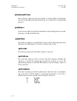


Figure E-2. Patch Converter Panel Cable, 087-2143-00x
Installation
To install the Patch Converter Panel and converter cable, follow these steps:
1.
Determine the desired location. The patch panel should be positioned
close enough to Access-T 1500 to allow the converter cable to reach.
The patch panel requires only 1.75 vertical inches of rack space (one
rack position).
2.
The patch panel includes a pair of mounting ears which support
either 19-inch or 23-inch equipment racks. Using the hardware pro-
vided, install the mounting ears on the sides of the patch panel in the
appropriate orientation for the rack width and desired projection.
3.
Mount the patch panel securely in the rack.
Pxx
MULTI-LINE
Pxx
MULTI-LINE
P3
P4
P5
50
50
25
25
26
26
1
1
1
1
1
26
26
26
25
25
25
50
50
50
087-2143-00x
ACST-0351-005
Appendix E
June 1996
Access-T 1500 Accessory Kits
E-3


