


Transmission Facilities
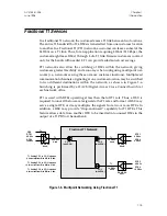
T1 signals are transmitted primarily over standard twisted-pair copper wire.
Signal loss on the wire is approximately 5 or 6 dB per 1000 feet. Repeaters are
employed every 6000 feet along the transmission facility to compensate for the
signal losses and to ensure an adequate signal level at the Network Interface
(the termination of the T1 line at the customer premises). AT&T specifies the
maximum distance between the CSU and the last repeater to be 3000 feet;
Access-T CSUs accurately regenerate a -27 dB signal (equivalent to the attenu-
ation over 5000 feet of cable). Figure 1-2 shows one end of a typical T1 link.
T1 may also be transmitted via satellites, digital microwave radios, fiber optic
systems, and coaxial cable modems. In the carrier networks, T1 signals may be
multiplexed into even higher-speed signals (e.g., T3).
Figure 1-1. AMI Line Coding
Figure 1-2. One End of a Typical T1 Link
Bits
Signal
0
0
0
1
1
0
1
1
Customer Premises Equipment
T1 Line
6000 ft. max.
3000 ft. max.
Network
Interface (NI)
Repeater
Repeater
DTE
CSU
655 ft. max.
ACST-0351-005
Chapter 1
June 1996
Introduction
1-5


