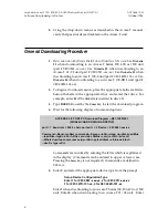
Table B. RDL Framing Format
FRAME #
F-BITS
DATALINK
CRC/ALARM
DATALINK
1-4
1
D/L
CRC-4
D/L
5-8
1
D/L
CRC-4
D/L
9-12
1
D/L
CRC-4
D/L
13-16
1
D/L
CRC-4
D/L
17-20
0
D/L
R-ALARM
D/L
RDL Framing Format
The RDL bit stream, shown in Table B, uses one bit per T1 frame, resulting in an 8
KHz channel. (Note that the RDL frame numbers have no correspondence to T1
frame numbers.) The RDL multiframe is 20 frames in length; each frame has 10 data
link bits, 5 alignment bits, 4 CRC-4 bits, and 1 remote alarm indication bit.
When RDL framing is lost (or regained), Access-T RDL sets (or clears) the alarm
bit in the RDL register byte, which in turn toggles the R-ALARM bit shown in
Table B. Access-T RDL declares LOF when the RDL frame remains out of sync
for 2.5 seconds.
RDL Data Rates
The RDL takes a portion of the bandwidth from the FT1 payload. The RDL data
stream is sent and received over the line, but does not appear at the DTE port. This
means that the FT1 data rate on the line is different from the rate seen at the DTE
port. The difference depends on which of the two RDL modes—Extra DS0 Mode
or Robbed-Bit Mode—is selected. The actual rate at the DTE port will always be
shown on the
SYSTEM—DS0 CONFIGURATION—CHANGE MAP x
screen, as
DATA=
[rate],
whereas the FT1 data rate to and from the line is always in terms of the number of
DS0s set in the current map (either Nx56 or Nx64).
The two RDL modes are explained below.
Extra DS0 Mode
In this mode, an entire DS0 is used for the RDL function, although only 8 kbps
is used to create the data link. Thus, the data rate seen at the DTE port will be
Larscom Incorporated
ACST-0351-S53
Supplement 3, ACST-0351-005
December 1996
10


