


3.8.1.1 TPM instantiation information
This device contains two low power TPM modules (TPM). All TPM modules in the
device are configured only as basic TPM function, do not support quadrature decoder
function, and all can be functional in Stop/VLPS mode. The clock source is either
external or internal in Stop/VLPS mode.
The following table shows how these modules are configured.
Table 3-31. TPM configuration
TPM instance
Number of channels
Features/usage
TPM0
2
Basic TPM,functional in Stop/VLPS mode
TPM1
2
Basic TPM,functional in Stop/VLPS mode
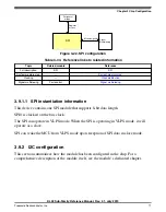
There are several connections to and from the TPMs in order to facilitate customer use
cases. For complete details on the TPM module interconnects please refer to the
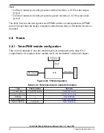
3.8.1.2 Clock options
The TPM blocks are clocked from a single TPM clock that can be selected from
OSCERCLK, MCGIRCLK, or MCGFLLCLK. The selected source is controlled by
SIM_SOPT2[TPMSRC] .
Each TPM also supports an external clock mode (TPM_SC[CMOD]=1x) in which the
counter increments after a synchronized (to the selected TPM clock source) rising edge
detect of an external clock input. The available external clock (either TPM_CLKIN0 or
TPM_CLKIN1) is selected by SIM_SOPT4[TPMxCLKSEL] control register. To
guarantee valid operation the selected external clock must be less than half the frequency
of the selected TPM clock source.
3.8.1.3 Trigger options
Each TPM has a selectable trigger input source controlled by the
TPMx_CONF[TRGSEL] field to use for starting the counter and/or reloading the
counter. The options available are shown in the following table.
Table 3-32. TPM trigger options
TPMx_CONF[TRGSEL]
Selected source
0000
External trigger pin input (EXTRG_IN)
Table continues on the next page...
Chapter 3 Chip Configuration
KL02 Sub-Family Reference Manual, Rev. 2.1, July 2013
Freescale Semiconductor, Inc.
67
Содержание KKL02Z32CAF4R
Страница 2: ...KL02 Sub Family Reference Manual Rev 2 1 July 2013 2 Freescale Semiconductor Inc...
Страница 24: ...KL02 Sub Family Reference Manual Rev 2 1 July 2013 24 Freescale Semiconductor Inc...
Страница 36: ...Orderable part numbers KL02 Sub Family Reference Manual Rev 2 1 July 2013 36 Freescale Semiconductor Inc...
Страница 76: ...Human machine interfaces HMI KL02 Sub Family Reference Manual Rev 2 1 July 2013 76 Freescale Semiconductor Inc...
Страница 94: ...Module clocks KL02 Sub Family Reference Manual Rev 2 1 July 2013 94 Freescale Semiconductor Inc...
Страница 142: ...Functional description KL02 Sub Family Reference Manual Rev 2 1 July 2013 142 Freescale Semiconductor Inc...
Страница 188: ...Memory map and register descriptions KL02 Sub Family Reference Manual Rev 2 1 July 2013 188 Freescale Semiconductor Inc...
Страница 214: ...Application information KL02 Sub Family Reference Manual Rev 2 1 July 2013 214 Freescale Semiconductor Inc...
Страница 222: ...Memory map register descriptions KL02 Sub Family Reference Manual Rev 2 1 July 2013 222 Freescale Semiconductor Inc...
Страница 256: ...Memory map and register definition KL02 Sub Family Reference Manual Rev 2 1 July 2013 256 Freescale Semiconductor Inc...
Страница 300: ...Functional description KL02 Sub Family Reference Manual Rev 2 1 July 2013 300 Freescale Semiconductor Inc...
Страница 532: ...Functional description KL02 Sub Family Reference Manual Rev 2 1 July 2013 532 Freescale Semiconductor Inc...
Страница 534: ...KL02 Sub Family Reference Manual Rev 2 1 July 2013 534 Freescale Semiconductor Inc...


