


30.4.1.5 Repeated START signal
The master may generate a START signal followed by a calling command without
generating a STOP signal first. This action is called a repeated START. The master uses
a repeated START to communicate with another slave or with the same slave in a
different mode (transmit/receive mode) without releasing the bus.
30.4.1.6 Arbitration procedure
The I2C bus is a true multimaster bus that allows more than one master to be connected
on it.
If two or more masters try to control the bus at the same time, a clock synchronization
procedure determines the bus clock. The bus clock's low period is equal to the longest
clock low period, and the high period is equal to the shortest one among the masters.
The relative priority of the contending masters is determined by a data arbitration
procedure. A bus master loses arbitration if it transmits logic level 1 while another master
transmits logic level 0. The losing masters immediately switch to slave receive mode and
stop driving SDA output. In this case, the transition from master to slave mode does not
generate a STOP condition. Meanwhile, hardware sets a status bit to indicate the loss of
arbitration.
30.4.1.7 Clock synchronization
Because wire AND logic is performed on SCL, a high-to-low transition on SCL affects
all devices connected on the bus. The devices start counting their low period and, after a
device's clock has gone low, that device holds SCL low until the clock reaches its high
state. However, the change of low to high in this device clock might not change the state
of SCL if another device clock is still within its low period. Therefore, the synchronized
clock SCL is held low by the device with the longest low period. Devices with shorter
low periods enter a high wait state during this time; see the following diagram. When all
applicable devices have counted off their low period, the synchronized clock SCL is
released and pulled high. Afterward there is no difference between the device clocks and
the state of SCL, and all devices start counting their high periods. The first device to
complete its high period pulls SCL low again.
Chapter 30 Inter-Integrated Circuit (I2C)
KL02 Sub-Family Reference Manual, Rev. 2.1, July 2013
Freescale Semiconductor, Inc.
485
Содержание KKL02Z32CAF4R
Страница 2: ...KL02 Sub Family Reference Manual Rev 2 1 July 2013 2 Freescale Semiconductor Inc...
Страница 24: ...KL02 Sub Family Reference Manual Rev 2 1 July 2013 24 Freescale Semiconductor Inc...
Страница 36: ...Orderable part numbers KL02 Sub Family Reference Manual Rev 2 1 July 2013 36 Freescale Semiconductor Inc...
Страница 76: ...Human machine interfaces HMI KL02 Sub Family Reference Manual Rev 2 1 July 2013 76 Freescale Semiconductor Inc...
Страница 94: ...Module clocks KL02 Sub Family Reference Manual Rev 2 1 July 2013 94 Freescale Semiconductor Inc...
Страница 142: ...Functional description KL02 Sub Family Reference Manual Rev 2 1 July 2013 142 Freescale Semiconductor Inc...
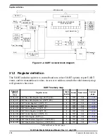
Страница 188: ...Memory map and register descriptions KL02 Sub Family Reference Manual Rev 2 1 July 2013 188 Freescale Semiconductor Inc...
Страница 214: ...Application information KL02 Sub Family Reference Manual Rev 2 1 July 2013 214 Freescale Semiconductor Inc...
Страница 222: ...Memory map register descriptions KL02 Sub Family Reference Manual Rev 2 1 July 2013 222 Freescale Semiconductor Inc...
Страница 256: ...Memory map and register definition KL02 Sub Family Reference Manual Rev 2 1 July 2013 256 Freescale Semiconductor Inc...
Страница 300: ...Functional description KL02 Sub Family Reference Manual Rev 2 1 July 2013 300 Freescale Semiconductor Inc...
Страница 532: ...Functional description KL02 Sub Family Reference Manual Rev 2 1 July 2013 532 Freescale Semiconductor Inc...
Страница 534: ...KL02 Sub Family Reference Manual Rev 2 1 July 2013 534 Freescale Semiconductor Inc...


