


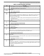
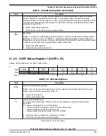


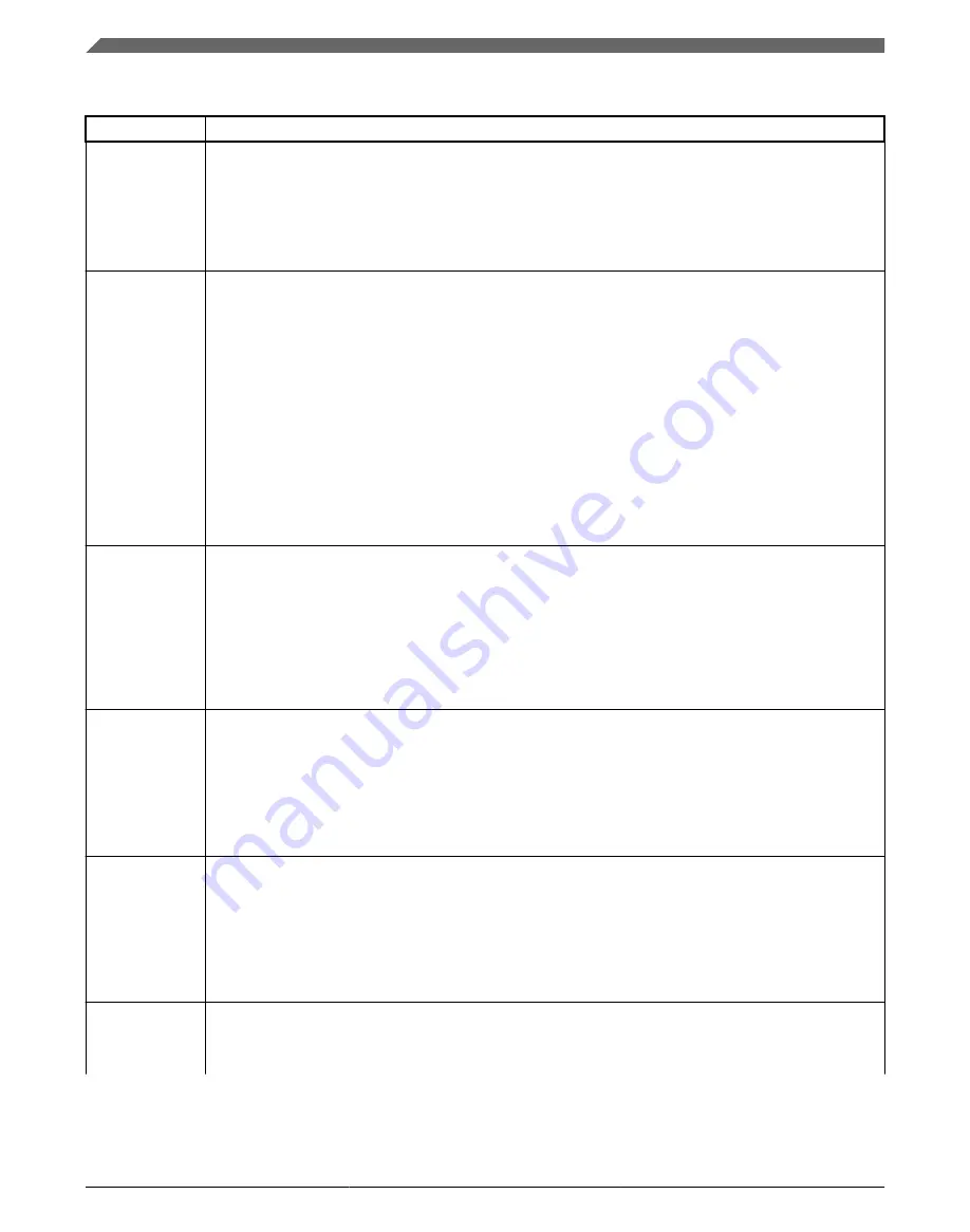
UARTx_S1 field descriptions (continued)
Field
Description
5
RDRF
Receive Data Register Full Flag
RDRF becomes set whenever the receive data buffer is full. To clear RDRF, read the UART data register
( UART_D).
0
Receive data buffer empty.
1
Receive data buffer full.
4
IDLE
Idle Line Flag
IDLE is set when the UART receive line becomes idle for a full character time after a period of activity.
When ILT is cleared, the receiver starts counting idle bit times after the start bit. If the receive character is
all 1s, these bit times and the stop bits time count toward the full character time of logic high, 10 to 13 bit
times, needed for the receiver to detect an idle line. When ILT is set, the receiver doesn't start counting
idle bit times until after the stop bits. The stop bits and any logic high bit times at the end of the previous
character do not count toward the full character time of logic high needed for the receiver to detect an idle
line.
To clear IDLE, write logic 1 to the IDLE flag. After IDLE has been cleared, it cannot become set again until
after a new character has been received and RDRF has been set. IDLE is set only once even if the
receive line remains idle for an extended period.
0
No idle line detected.
1
Idle line was detected.
3
OR
Receiver Overrun Flag
OR is set when a new serial character is ready to be transferred to the receive data buffer, but the
previously received character has not been read from UART_D yet. In this case, the new character, and
all associated error information, is lost because there is no room to move it into UART_D. To clear OR,
write a logic 1 to the OR flag.
0
No overrun.
1
Receive overrun (new UART data lost).
2
NF
Noise Flag
The advanced sampling technique used in the receiver takes three samples in each of the received bits. If
any of these samples disagrees with the rest of the samples within any bit time in the frame, the flag NF is
set at the same time as RDRF is set for the character. To clear NF, write logic one to the NF.
0
No noise detected.
1
Noise detected in the received character in UART_D.
1
FE
Framing Error Flag
FE is set at the same time as RDRF when the receiver detects a logic 0 where a stop bit was expected.
This suggests the receiver was not properly aligned to a character frame. To clear FE, write a logic one to
the FE flag.
0
No framing error detected. This does not guarantee the framing is correct.
1
Framing error.
0
PF
Parity Error Flag
PF is set at the same time as RDRF when parity is enabled (PE = 1) and the parity bit in the received
character does not agree with the expected parity value. To clear PF, write a logic one to the PF.
Table continues on the next page...
Register definition
KL02 Sub-Family Reference Manual, Rev. 2.1, July 2013
504
Freescale Semiconductor, Inc.
Содержание KKL02Z32CAF4R
Страница 2: ...KL02 Sub Family Reference Manual Rev 2 1 July 2013 2 Freescale Semiconductor Inc...
Страница 24: ...KL02 Sub Family Reference Manual Rev 2 1 July 2013 24 Freescale Semiconductor Inc...
Страница 36: ...Orderable part numbers KL02 Sub Family Reference Manual Rev 2 1 July 2013 36 Freescale Semiconductor Inc...
Страница 76: ...Human machine interfaces HMI KL02 Sub Family Reference Manual Rev 2 1 July 2013 76 Freescale Semiconductor Inc...
Страница 94: ...Module clocks KL02 Sub Family Reference Manual Rev 2 1 July 2013 94 Freescale Semiconductor Inc...
Страница 142: ...Functional description KL02 Sub Family Reference Manual Rev 2 1 July 2013 142 Freescale Semiconductor Inc...
Страница 188: ...Memory map and register descriptions KL02 Sub Family Reference Manual Rev 2 1 July 2013 188 Freescale Semiconductor Inc...
Страница 214: ...Application information KL02 Sub Family Reference Manual Rev 2 1 July 2013 214 Freescale Semiconductor Inc...
Страница 222: ...Memory map register descriptions KL02 Sub Family Reference Manual Rev 2 1 July 2013 222 Freescale Semiconductor Inc...
Страница 256: ...Memory map and register definition KL02 Sub Family Reference Manual Rev 2 1 July 2013 256 Freescale Semiconductor Inc...
Страница 300: ...Functional description KL02 Sub Family Reference Manual Rev 2 1 July 2013 300 Freescale Semiconductor Inc...
Страница 532: ...Functional description KL02 Sub Family Reference Manual Rev 2 1 July 2013 532 Freescale Semiconductor Inc...
Страница 534: ...KL02 Sub Family Reference Manual Rev 2 1 July 2013 534 Freescale Semiconductor Inc...


