


Maintenance and Specifications
If Something Seems Wrong
11
11-9
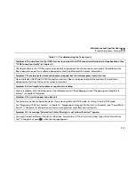
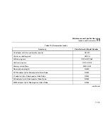
Table 11-1. Troubleshooting the Tester (cont.)
Symptom 6: The noise level on the OTDR trace has increased or the OTDR connector reflection has a large deadzone. (See
“OTDR Connection Quality” in Chapter 3.)
The fiber endface in the OTDR connector may be dirty or damaged. Clean the connector and inspect the endface with a
fiber video microscope. If an endface is damaged, contact Fluke Networks for service information.
Symptom 7: The reference test cords and adapters are good, but the reference power level is too low.
Clean the tester’s INPUT and OUTPUT connectors and use a fiber microscope to inspect the endfaces. If an endface is
damaged, contact Fluke Networks for service information.
Symptom 8: A loss/length test produces a negative loss reading.
There is a problem with the reference. Set the reference and test the cabling again. See “Diagnosing Loss/Length Test
Failures” in Chapter 6 for details.
Symptom 9: Test results appear to be incorrect.
The tester may not be configured correctly. If you are using Manual OTDR mode, try testing in Auto OTDR mode.
See “Diagnosing OTDR Test Failures” in Chapter 3, “Diagnosing Loss/Length Test Failures” in Chapter 6, and “Power Meter
Results” in Chapter 8 for information on how misconfigurations may affect your test results.
Symptom 10: The message “Selected test limit or fiber type is not valid with this test” appears.
You need to select a different test limit or fiber type. For details see “If the Test Limit or Fiber Type is Not Valid with the
Test” in Chapter 2 or press
H
when the message appears.
Содержание OF-500 OptiFiber
Страница 12: ...OF 500 OptiFiber Technical Reference Handbook x ...
Страница 18: ...OF 500 OptiFiber Technical Reference Handbook xvi ...
Страница 27: ...Getting Acquainted Powering the Tester 1 1 9 ajt20f eps Figure 1 1 Battery Pack Features ...
Страница 29: ...Getting Acquainted Verifying Operation 1 1 11 ajt56f eps Figure 1 2 Removing the Module ...
Страница 46: ...OF 500 OptiFiber Certifying OTDR Technical Reference Handbook 1 28 ...
Страница 95: ...Using the OTDR Running the OTDR Test 3 3 21 ajt33f eps Figure 3 12 Connecting the OTDR to Spooled Cable ...
Страница 133: ...Using the ChannelMap Function Running the Test 4 4 3 ajt55f eps Figure 4 2 ChannelMap Test Connections ...
Страница 136: ...OF 500 OptiFiber Certifying OTDR Technical Reference Handbook 4 6 ...
Страница 148: ...OF 500 OptiFiber Certifying OTDR Technical Reference Handbook 6 4 ajt61f eps Figure 6 2 Changing the Connector Adapter ...
Страница 192: ...OF 500 OptiFiber Certifying OTDR Technical Reference Handbook 6 48 ...
Страница 196: ...OF 500 OptiFiber Certifying OTDR Technical Reference Handbook 7 4 ajt03f eps Figure 7 2 Using the Visual Fault Locator ...
Страница 254: ...OF 500 OptiFiber Certifying OTDR Technical Reference Handbook 11 36 ...
Страница 256: ...OF 500 OptiFiber Certifying OTDR Technical Reference Handbook ...
Страница 261: ...Loss Test Methods Method A A 2 B B 3 ajt58f eps Figure B 1 Method A A 2 Reference and Test Connections singlemode shown ...
Страница 263: ...B 5 ajt59f eps Figure B 2 Method B A 1 Reference and Test Connections singlemode shown Loss Test Methods Method B A 1 B ...
Страница 265: ...Loss Test Methods Method C A 3 B B 7 ajt60f eps Figure B 3 Method C A 3 Reference and Test Connections singlemode shown ...
Страница 272: ...B 14 OF 500 OptiFiber Certifying OTDR Technical Reference Handbook ...
Страница 274: ...OF 500 OptiFiber Certifying OTDR Technical Reference Handbook C 2 ...
Страница 282: ...OF 500 OptiFiber Technical Reference Handbook 8 ...


