


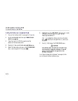


Using the Loss/Length Option
Testing in Loopback Mode
6
6-31
Table 6-7. Loopback Mode RESULTS Screen Features
Item Description
END 1-2
END 2-1
These refer to the direction of the test results. If
THIS END
in Setup is set to
END 1
,
END
1
is the fiber end
connected to the INPUT port. If
THIS END
in Setup is set to
END 2
,
END
2
is the fiber end connected to the
INPUT port.
When bi-directional testing is enabled, the tester shows results for both directions. If
THIS END
in Setup is set
to
END 1
,
END 1
is the fiber end connected to the INPUT port when the test was finished.
PASS:
The measurement in the column is within the limit.
FAIL:
The measurement in the column exceeds the limit.
RESULT
The loss, length, or propagation delay result for the fiber loop. Propagation delay is time taken for the signal
to travel from the tester's OUTPUT connector to the INPUT connector (minus the delay of the reference test
cords and adapters). "Too High" is shown if the loss is too high to measure. If loss is negative, set the
reference and test the cabling again. See Table 6-10 for details.
LIMIT
The maximum loss, length, or propagation delay allowed by the selected test limit.
MARGIN
The difference between the limit and the measured value. Margin is negative for measurements that fail.
N/A
The results show
N/A
for values not defined by the selected test limit.
Содержание OF-500 OptiFiber
Страница 12: ...OF 500 OptiFiber Technical Reference Handbook x ...
Страница 18: ...OF 500 OptiFiber Technical Reference Handbook xvi ...
Страница 27: ...Getting Acquainted Powering the Tester 1 1 9 ajt20f eps Figure 1 1 Battery Pack Features ...
Страница 29: ...Getting Acquainted Verifying Operation 1 1 11 ajt56f eps Figure 1 2 Removing the Module ...
Страница 46: ...OF 500 OptiFiber Certifying OTDR Technical Reference Handbook 1 28 ...
Страница 95: ...Using the OTDR Running the OTDR Test 3 3 21 ajt33f eps Figure 3 12 Connecting the OTDR to Spooled Cable ...
Страница 133: ...Using the ChannelMap Function Running the Test 4 4 3 ajt55f eps Figure 4 2 ChannelMap Test Connections ...
Страница 136: ...OF 500 OptiFiber Certifying OTDR Technical Reference Handbook 4 6 ...
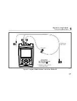
Страница 148: ...OF 500 OptiFiber Certifying OTDR Technical Reference Handbook 6 4 ajt61f eps Figure 6 2 Changing the Connector Adapter ...
Страница 192: ...OF 500 OptiFiber Certifying OTDR Technical Reference Handbook 6 48 ...
Страница 196: ...OF 500 OptiFiber Certifying OTDR Technical Reference Handbook 7 4 ajt03f eps Figure 7 2 Using the Visual Fault Locator ...
Страница 254: ...OF 500 OptiFiber Certifying OTDR Technical Reference Handbook 11 36 ...
Страница 256: ...OF 500 OptiFiber Certifying OTDR Technical Reference Handbook ...
Страница 261: ...Loss Test Methods Method A A 2 B B 3 ajt58f eps Figure B 1 Method A A 2 Reference and Test Connections singlemode shown ...
Страница 263: ...B 5 ajt59f eps Figure B 2 Method B A 1 Reference and Test Connections singlemode shown Loss Test Methods Method B A 1 B ...
Страница 265: ...Loss Test Methods Method C A 3 B B 7 ajt60f eps Figure B 3 Method C A 3 Reference and Test Connections singlemode shown ...
Страница 272: ...B 14 OF 500 OptiFiber Certifying OTDR Technical Reference Handbook ...
Страница 274: ...OF 500 OptiFiber Certifying OTDR Technical Reference Handbook C 2 ...
Страница 282: ...OF 500 OptiFiber Technical Reference Handbook 8 ...


