ELECTRICAL
Page G-7
Repair and Service Manual
Read all of Section B and this section before attempting any procedure. Pay particular attention to all Notes, Cautions and Warnings
Check power wire
The white power wire supplies power to the
entire fuse block.
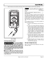
Firmly attach the black probe (-) to the battery post with
the black wire attached and the red probe (+) to the white
wire terminal at the fuse block. A reading of battery volt-
age indicates that the power wire is in good condition.
Check fuse
Check each fuse for continuity. If a new fuse is required,
replace with one of the same amperage.
ACCESSORY WIRING
After determining that there is power to the fuse panel,
and the fuse is good, continue checking the circuit using
the procedures previously used to check the power sup-
ply, i.e. loose or rusted connections, bare wires, continu-
ity of the wiring from terminal to terminal, operating
condition of switch, etc.
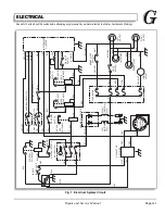
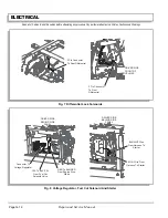
Use the wiring diagram (Ref Fig. 1 on page G-1) to check
correct wiring and wire routing. If there is power at the
fuse end of the wire, there must also be power at the
other end of the wire at the switch or electrical accessory,
and eventually at the ground connection. Electricity must
flow from the fuse panel through the full length of the cir-
cuit to the ground connection. Any interruption of electri-
cal flow must be corrected, whether by repairing or
replacing the wire, the switch or accessory.
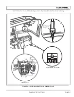
INSTRUMENT CLUSTER
The instrument cluster contains indicator lights for 4
Wheel Drive, Parking Brake, Fuel Gauge, Front and Rear
Differential Locks, Low Oil Pressure and a digital hour
meter. The cluster is not repairable and must be replaced
if there is a malfunction within the unit (Ref Fig. 4 on
page G-9).
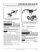
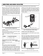
The Four Wheel Drive Indicator is operated by a prox-
imity switch and the switch can be tested as described in
the ‘DIRECTION SELECTOR’ section of this manual.
The switch does not operate the four wheel drive, only
the indicator light. Similarly the Parking Brake Indicator
uses the same proximity switch that can be tested in the
same way. If the switch is good, check for voltage at the
instrument cluster connector. If voltage is present but the
indicator is not working, replace the instrument cluster. If
voltage is not present, verify that the switch is correctly
oriented in relation to the operating component and that
the wire harness does not have an internal break.
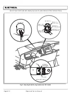
The Fuel Gauge Sending unit test is described in the
‘FUEL SYSTEM’. If the sending unit and the wiring from
the unit to the instrument cluster connector is satisfac-
tory, replace the instrument cluster (Ref Fig. 6 on page
G-11).
The Differential Lock indicator and switches can be
checked by operating them and observing the solenoids
at the differentials. If the solenoid operates but the indica-
tor does not, check for voltage at the instrument cluster
connector. If voltage is present but the indicator is not
working, replace the instrument cluster. If solenoids do
not function, verify that the switches have continuity
when closed and replace switch if continuity is not
present. If the switch functions correctly, and if battery
voltage is not present, check the fuse and that the wire
harness does not have an internal break.
Low Oil Pressure Gauge With the engine off, check for
continuity between the oil pressure switch’s two termi-
nals. Continuity should be indicated. If not replace the
switch. Check that there is adequate oil in the engine and
start engine. Shortly after starting, the continuity across
the oil pressure switch should be lost as the switch opens
in response to oil pressure. If not, replace the switch.
With the switch known to be good, the indicator light
should illuminate at the instrument cluster, when the key
switch is ON but the engine is not running. If not check
the gray wire at the instrument cluster for battery voltage.
If battery voltage is present, replace the instrument clus-
ter. If battery voltage is not present, check that wire har-
ness does not have an internal break.
DIFFERENTIAL LOCK SOLENOIDS
Check operation of switches as described in INSTRU-
MENT CLUSTER The Differential Lock (Ref Fig. 7 on
page G-12). With the switch in the engaged position,
check for voltage at the differential lock solenoid connec-
tor. If voltage is present, replace solenoid. If battery volt-
age is not present, check the fuse and that the wire
harness does not have an internal break. Replace sole-
noid.
Содержание ST 4X4
Страница 6: ...Page iv Repair and Service Manual TABLE OF CONTENTS Notes...
Страница 10: ...Repair and Service Manual SAFETY INFORMATION Page viii Notes...
Страница 12: ...GENERAL INFORMATION ROUTINE MAINTENANCE Page A ii Repair and Service Manual Notes...
Страница 24: ...SAFETY Page B ii Repair and Service Manual Notes...
Страница 34: ...BODY AND TRUCKBED Page C ii Repair and Service Manual Notes...
Страница 50: ...BRAKES Page D ii Repair and Service Manual Notes...
Страница 68: ...CONTINUOUSLY VARIABLE TRANSMISSION CVT Page E ii Repair and Service Manual Notes...
Страница 74: ...DIRECTION AND DRIVE SELECTOR Page F ii Repair and Service Manual Notes...
Страница 80: ...ELECTRICAL Page G ii Repair and Service Manual Notes...
Страница 114: ...FRONT SUSPENSION AND STEERING Page J ii Repair and Service Manual Notes...
Страница 128: ...FUEL SYSTEM Page K ii Repair and Service Manual Notes...
Страница 136: ...PAINT Page L ii Repair and Service Manual Notes...
Страница 142: ...REAR AXLE AND SUSPENSION Page M ii Repair and Service Manual Notes...
Страница 152: ...SPEED CONTROL Page N ii Repair and Service Manual Notes...
Страница 160: ...TROUBLESHOOTING Page P ii Repair and Service Manual Notes...
Страница 168: ...WHEELS AND TIRES Page R ii Repair and Service Manual Notes...
Страница 174: ...GENERAL SPECIFICATIONS Page S ii Repair and Service Manual Notes...
Страница 180: ...LIMITED WARRANTY Page T ii Repair and Service Manual Notes...
Страница 182: ...Page T 2 Repair and Service Manual LIMITED WARRANTY Notes...

