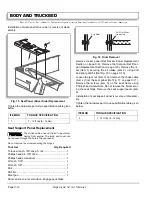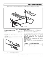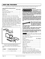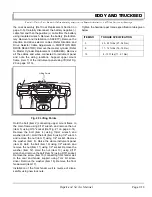
BRAKES
Page D-8
Repair and Service Manual
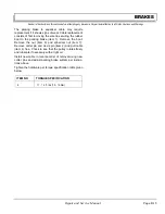
Read all of Section B and this section before attempting any procedure. Pay particular attention to all Notes, Cautions and Warnings
A backing plate assembly that shows any indication
of galling or gouging is not repairable and must be
replaced with a new wheel brake assembly. Always
replace wheel brake assemblies in pairs.
Inspect the brake drum (item 1) (Ref Fig. 5 on page D-7).
Look for a blue coloration or blistered paint that would
indicate that it has overheated. Check for evidence of
scoring/gouging. Check for excessive wear indicated by
the friction surface being significantly worn and leaving a
ledge of unworn drum. If any of these problems are
found, the drum must be replaced.
Clean the backing plate (item 16) with a commercially
available brake cleaner.
Inspect the backing plate (item 16). Inspect for gouges,
galling or other damage, particularly where the backing
plate (item 16) is contacted by the brake shoes (item 13).
Be sure shoe ledges are smooth and free of rough
edges. Replace both wheel brake assemblies (item 8) if
any gouges or galling is found.
It is normal for the shoes to show more wear at
the leading and trailing edges. If the brake
shoe thickness is approaching .06" (1.5 mm), it is recom-
mended that the shoes be replaced.
Measure the brake shoe (item 13) thickness. Measure at
the most worn area. Brake shoes must be replaced when
friction material thickness is .06" (1.5 mm) at any point on
the shoe. It is recommended that the brake shoe springs
(item 10, 11) and brake adjusters (item 17) be replaced
when installing new brake shoes.
Check springs for loss of tension and damage. Replace
weak springs and any damaged or badly worn parts.
Check adjuster (item 17) operation. Insure that each
adjuster will move with approximately 30 - 50 in. lbs (3.4 -
5.6 Nm) of torque. If adjusters are frozen, badly worn or
loose, replace the adjuster assembly.
Replace the wheel cylinder (item 14) if there is any sign
of leakage. Insure that the parking lever and strut assem-
bly moves freely. If necessary, this assembly can be ser-
viced as follows:
Disassemble by removing the C-clip. Wire brush contact
surfaces to remove any corrosion and contaminants.
Lightly grease the pin and contact surfaces before re-
assembly.
Reassembly
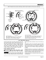
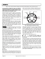
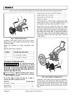
Apply a light coat of high temperature lubricant to shoe
support points on the backing plate (item 16), (Ref Fig. 6
on page D-8) and (Ref Fig. 5 on page D-7) to adjuster pin
(item 18), and to anchor. Position the adjusters (item 17)
so that the pins (item 18) are at the 12 o'clock position.
If the wheel cylinder (item 14) was removed, install it to
the backing plate (item 16). Insert and tighten the wheel
cylinder mounting bolts (item 15). Position shoes (item
13) on backing plate (item 16) and install hold-down
springs (item 12). Install parking brake strut with tab on
strut engaged in brake shoe web. Place upper end of
shoe webs against wheel cylinder, and install upper
shoe-to-shoe spring (item 10).
Install lower shoe-to-shoe spring (item 11).
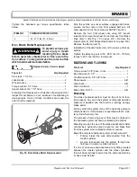
Use great care when installing axle
shaft. The shaft must pass through an
internal oil seal.
Insert axle shaft (item 9) through brake assembly (item
8). Hold the axle and insert into axle tube (item 7). Keep
axle centered in the tube and engage it with the internal
spline within the differential. Align the four mounting
holes in the pillow block bearing with the brake assembly
mounting holes and the holes in the axle tube flange.
Install bolts (item 6) with a 1/2" socket. Connect the
brake line (item 5).
Install parking brake cable (item 4) using new cotter pins.
Pre-adjust shoes by rotating adjuster bolt (item 19) away
from the axle until shoes contact drum and then back off
just enough to eliminate drag.
Fig. 6 Backing Plate Lubrication Points
Backing Plate
Lubricate
(3) Bosses
Each Side
Lubricate
(3) Bosses
Each Side
Fixed Anchor
Wheel Cylinder
Adjuster
Adjuster Pin
Содержание ST 4X4
Страница 6: ...Page iv Repair and Service Manual TABLE OF CONTENTS Notes...
Страница 10: ...Repair and Service Manual SAFETY INFORMATION Page viii Notes...
Страница 12: ...GENERAL INFORMATION ROUTINE MAINTENANCE Page A ii Repair and Service Manual Notes...
Страница 24: ...SAFETY Page B ii Repair and Service Manual Notes...
Страница 34: ...BODY AND TRUCKBED Page C ii Repair and Service Manual Notes...
Страница 50: ...BRAKES Page D ii Repair and Service Manual Notes...
Страница 68: ...CONTINUOUSLY VARIABLE TRANSMISSION CVT Page E ii Repair and Service Manual Notes...
Страница 74: ...DIRECTION AND DRIVE SELECTOR Page F ii Repair and Service Manual Notes...
Страница 80: ...ELECTRICAL Page G ii Repair and Service Manual Notes...
Страница 114: ...FRONT SUSPENSION AND STEERING Page J ii Repair and Service Manual Notes...
Страница 128: ...FUEL SYSTEM Page K ii Repair and Service Manual Notes...
Страница 136: ...PAINT Page L ii Repair and Service Manual Notes...
Страница 142: ...REAR AXLE AND SUSPENSION Page M ii Repair and Service Manual Notes...
Страница 152: ...SPEED CONTROL Page N ii Repair and Service Manual Notes...
Страница 160: ...TROUBLESHOOTING Page P ii Repair and Service Manual Notes...
Страница 168: ...WHEELS AND TIRES Page R ii Repair and Service Manual Notes...
Страница 174: ...GENERAL SPECIFICATIONS Page S ii Repair and Service Manual Notes...
Страница 180: ...LIMITED WARRANTY Page T ii Repair and Service Manual Notes...
Страница 182: ...Page T 2 Repair and Service Manual LIMITED WARRANTY Notes...

