SPEED CONTROL
Page N-5
Repair and Service Manual
Read all of Section B and this section before attempting any procedure. Pay particular attention to all Notes, Cautions and Warnings
Refer to SAFETY section before you start.
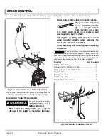
Park the vehicle on a level surface, engage park brake.
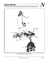
Remove cotter pin (item 1) using needle nose pliers and
clevis pin (item 2) using ball peen hammer (Ref Fig. 5 on
page N-4). Detach the accelerator cable (item 3).
Remove the extension spring (item 4) using needle nose
pliers. Hold the bolt (item 5) using 3/4" wrench and
remove the nut (item 6) using 3/4" deep well socket.
Remove the washer (item 7). Remove the accelerator
pedal (item 8).
Installation of the accelerator pedal is the reverse of dis-
assembly using new cotter pin and new locknut.
Inspect the bolt (item 5) for corrosion that could cause
binding. Both bushings (item 9) and bolt (item 5) must be
replaced with new ones if corrosion or wear is found.
Tighten the hardware per torque specification table given
below.
ROAD TEST
Install the negative (-) battery cable.
Test drive the vehicle and confirm that the compression
spring adjustment results in the maximum governed
speed specified in the GENERAL SPECIFICATIONS
section. Determine speed by measuring the time it takes
to travel a known set distance with vehicle at maximum
speed. Enter time and distance into this formula to calcu-
late speed:
Rate (in MPH) = (Distance in feet ÷ 5280) ÷ (Time in
seconds ÷ 3600)
or
Rate (in KPH) = (Distance in meters ÷ 1000) ÷ (Time in
seconds ÷ 3600)
For example:
(300 ft. ÷ 5280) ÷ (8.18 sec. ÷ 3600) = 25 MPH
or
(100 m ÷ 1000) ÷ (9 sec. ÷ 3600) = 40 KPH
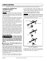
If the speed is not within the specified speed range, stop
the vehicle and adjust the governor compression spring.
Tightening the spring results in a speed increase while
loosening it will result in a speed decrease. Repeat road
test and adjustment procedure until the factory recom-
mended governed speed is achieved.
Install new safety seal on governor after calibrating the
vehicle.
TROUBLESHOOTING
Erratic acceleration and performance that does not
include a notable increase in governed speed, may indi-
cate the need for a linkage adjustment.
Symptoms that include an increase in governed speed
indicate:
•
Worn components in the governor system
•
Improper adjustment of linkage system
•
Loose adjustment of accelerator cable and gover-
nor cable.
Symptoms that include a decrease in governed speed
indicate:
•
Compression spring has lost its temper and needs
replacement with correct compression spring
•
Improper adjustment of linkage system
•
Loose adjustment of accelerator cable and gover-
nor cable
•
Worn components in the governor system.
ITEM NO
TORQUE SPECIFICATION
6
20 - 25 ft. lbs
.
(27 - 34 Nm)
Содержание ST 4X4
Страница 6: ...Page iv Repair and Service Manual TABLE OF CONTENTS Notes...
Страница 10: ...Repair and Service Manual SAFETY INFORMATION Page viii Notes...
Страница 12: ...GENERAL INFORMATION ROUTINE MAINTENANCE Page A ii Repair and Service Manual Notes...
Страница 24: ...SAFETY Page B ii Repair and Service Manual Notes...
Страница 34: ...BODY AND TRUCKBED Page C ii Repair and Service Manual Notes...
Страница 50: ...BRAKES Page D ii Repair and Service Manual Notes...
Страница 68: ...CONTINUOUSLY VARIABLE TRANSMISSION CVT Page E ii Repair and Service Manual Notes...
Страница 74: ...DIRECTION AND DRIVE SELECTOR Page F ii Repair and Service Manual Notes...
Страница 80: ...ELECTRICAL Page G ii Repair and Service Manual Notes...
Страница 114: ...FRONT SUSPENSION AND STEERING Page J ii Repair and Service Manual Notes...
Страница 128: ...FUEL SYSTEM Page K ii Repair and Service Manual Notes...
Страница 136: ...PAINT Page L ii Repair and Service Manual Notes...
Страница 142: ...REAR AXLE AND SUSPENSION Page M ii Repair and Service Manual Notes...
Страница 152: ...SPEED CONTROL Page N ii Repair and Service Manual Notes...
Страница 160: ...TROUBLESHOOTING Page P ii Repair and Service Manual Notes...
Страница 168: ...WHEELS AND TIRES Page R ii Repair and Service Manual Notes...
Страница 174: ...GENERAL SPECIFICATIONS Page S ii Repair and Service Manual Notes...
Страница 180: ...LIMITED WARRANTY Page T ii Repair and Service Manual Notes...
Страница 182: ...Page T 2 Repair and Service Manual LIMITED WARRANTY Notes...

