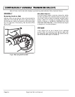
CONTINUOUSLY VARIABLE TRANSMISSION (CVT)
Page E-2
Repair and Service Manual
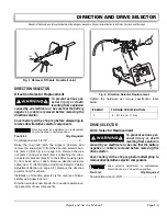
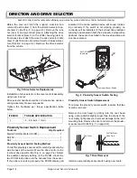
Read all of Section B and this section before attempting any procedure. Pay particular attention to all Notes, Cautions and Warnings
As the drive belt starts to rotate, the driven clutch starts to
rotate. As the speed of the drive clutch increases and the
belt starts to climb the drive clutch sheaves, the driven
clutch responds by being forced open by the belt which
rides lower in the driven clutch sheaves. The sheaves
overcome the pressure exerted by the torsion spring and
cam.
As the driven clutch slows, the belt rides lower in the
drive clutch sheaves. The driven clutch compensates by
closing in response to the torsion spring and cam forcing
the belt outwards.
Increased Load
When a vehicle traveling at governed speed begins to
climb a grade or is subjected to other increased load con-
ditions, a change in wheel speed is detected by the
clutch system and the drive belt seeks a position where it
can achieve adequate friction to overcome the load
change. The belt moves outwards on the driven clutch
which closes due to the torsion spring moving the move-
able sheave against the torque ramps. The movement of
the drive belt overcomes some of the centrifugal force
exerted by the cams in the drive clutch. This forces the
belt lower into the drive clutch which increases the drive
ratio. This ‘downshifting’ applies more torque to the rear
axle without an appreciable change to the engine speed
since the governor opens the carburetor in direct
response to the reduction in ground speed.
Equilibrium
The CVT functions because the drive and driven clutches
maintain equilibrium. Clutch sets are tuned to the vehicle
that they are designed to operate. Changes in vehicle
weight or desired performance characteristics require
that both clutches be tuned to the needs of the vehicle
and remain compatible with each other.
Drive Clutch Replacement
To prevent serious per-
sonal injury or death
resulting from inadvert-
ant movement of the vehicle:
Disable the electrical system before attempting to
remove the drive belt to prevent the engine from
inadvertently starting.
Do not allow fingers to become trapped between
the belt and clutch sheave.
To prevent burns and other possible injuries, be
sure that the engine and exhaust components
have cooled before attempting any service.
To prevent serious personal injury or death, use
only sockets designed for use with an impact
wrench. Never use a socket intended for use with
hand tools.
To prevent damage to the clutch, be
sure to remove all grease from the body
of the clutch since grease penetrating the seal may cause pre-
mature clutch failure.
Do not install the bolt with an impact wrench.
In some extreme cases, the clutch may not
separate from the crankshaft using the clutch
puller. Remove the clutch puller and fill the cavity with grease.
Replace the clutch puller and tighten it with the impact wrench.
The combined mechanical and hydraulic effect will remove the
clutch. Remove all excess grease.
Tool List
Qty. Required
Torque wrench, 1/2" drive, ft. lbs. ................................ 1
Impact wrench, 1/2" drive ............................................ 1
Impact socket, 1 1/8", 1/2" drive .................................. 1
Wrench, 17mm ............................................................ 1
Plastic faced hammer .................................................. 1
Clutch puller (P/N 19779-G2) ...................................... 1
Thread locking adhesive........................................... AR
Remove the bolts (item 1) and remove the CVT cover
(item 2). Remove the drive belt (item 3). (Ref Removing
the Drive Belt section on page E-4).
Remove the drive clutch bolt (item 4), lock washer (item
5) and pilot washer (item 6) (Ref Fig. 2 on page E-3).
Insert a greased clutch puller and tighten (clockwise)
using an impact wrench which will remove the drive
clutch (item 7) from the engine crankshaft.
Installation of the drive clutch is the reverse of disassem-
bly. Clean both the engine crankshaft and the drive clutch
bore. Slide the clutch onto the engine crankshaft and
rotate the clutch while lightly pushing the moveable
sheave in and out several times to seat the clutch with
the tapered crankshaft.
Apply thread locking adhesive to the threads of the clutch
bolt (item 4) before installing (Ref Fig. 2 on page E-3).
Tighten the hardware per torque specification table given
below.
!
!
ITEM NO
TORQUE SPECIFICATION
1
20 - 30 in. lbs (2 - 3 Nm)
4
40 ft. lbs (55 Nm)
Содержание ST 4X4
Страница 6: ...Page iv Repair and Service Manual TABLE OF CONTENTS Notes...
Страница 10: ...Repair and Service Manual SAFETY INFORMATION Page viii Notes...
Страница 12: ...GENERAL INFORMATION ROUTINE MAINTENANCE Page A ii Repair and Service Manual Notes...
Страница 24: ...SAFETY Page B ii Repair and Service Manual Notes...
Страница 34: ...BODY AND TRUCKBED Page C ii Repair and Service Manual Notes...
Страница 50: ...BRAKES Page D ii Repair and Service Manual Notes...
Страница 68: ...CONTINUOUSLY VARIABLE TRANSMISSION CVT Page E ii Repair and Service Manual Notes...
Страница 74: ...DIRECTION AND DRIVE SELECTOR Page F ii Repair and Service Manual Notes...
Страница 80: ...ELECTRICAL Page G ii Repair and Service Manual Notes...
Страница 114: ...FRONT SUSPENSION AND STEERING Page J ii Repair and Service Manual Notes...
Страница 128: ...FUEL SYSTEM Page K ii Repair and Service Manual Notes...
Страница 136: ...PAINT Page L ii Repair and Service Manual Notes...
Страница 142: ...REAR AXLE AND SUSPENSION Page M ii Repair and Service Manual Notes...
Страница 152: ...SPEED CONTROL Page N ii Repair and Service Manual Notes...
Страница 160: ...TROUBLESHOOTING Page P ii Repair and Service Manual Notes...
Страница 168: ...WHEELS AND TIRES Page R ii Repair and Service Manual Notes...
Страница 174: ...GENERAL SPECIFICATIONS Page S ii Repair and Service Manual Notes...
Страница 180: ...LIMITED WARRANTY Page T ii Repair and Service Manual Notes...
Страница 182: ...Page T 2 Repair and Service Manual LIMITED WARRANTY Notes...

