ELECTRICAL
Page G-4
Repair and Service Manual
Read all of Section B and this section before attempting any procedure. Pay particular attention to all Notes, Cautions and Warnings
TESTING STARTING CIRCUIT
To prevent the possibili-
ty of severe injury or
d e a t h r e s u l t in g f ro m
vehicle inadvertently starting, disconnect battery for
steps 2 through 9 (see Section B).
If any DVOM readings indicate a faulty wire, it
is recommended that the condition of the termi-
nals and wire junction be examined. A faulty wire should be
replaced with one of the same gauge and color and wired
between the correct components and wire tied to the harness
bundle. The faulty wire should be cut back close to the harness
and the ends protected with vinyl electrical tape.
Most DVOM’s can be set to give an audible signal if continuity
is present, however readings will generally indicate near
Ω.
Readings greater than 1K
Ω
may indicate a marginal conductor
or joint.
Tool List
Qty. Required
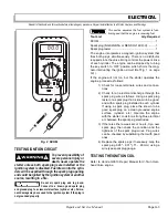
DVOM.......................................................................... 1
If the engine does not rotate, proceed as follows:
1. Check for a good ground between the battery nega-
tive (-), the frame and the engine.
2. Check that vehicle is in neutral (Ref Fig. 1 on page G-
1).
3. Check the battery for a voltage reading which should
be between 12.2 and 12.5 volts. Inspect for loose or
dirty battery post connections.
4. Check for a blown in line fuse and replace if neces-
sary with the recommended amp fuse.
5. Check for loose wires at all terminal connections.
6. Check the complete electrical system for correct cir-
cuitry.
7. Inspect for worn insulation or bare wires touching the
frame. Bare wires will cause a short circuit.
8. Set the DVOM to the ohms (
Ω)
scale. A meter read-
ing of “0”
Ω
indicates continuity. Check for continuity
for white (WHT) wire from battery positive terminal (+)
to the key switch terminal (B) white (WHT) wire. If
continuity is not indicated, there is a fault in the wiring
harness. Check for continuity of the key switch.
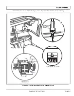
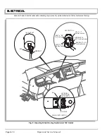
Remove key switch plate from instrument panel (Ref
Instrument Panel Replacement section in BODY AND
TRUCKBED). Detach electrical plug from key switch.
Place positive (+) probe on terminal (B) of white
(WHT) wire and negative (-) probe on terminal (S) of
black/white (BLK/WHT) wire. The reading on the
meter should be “0”
Ω
with the switch key in the ‘ON’
position and OL with the switch in the ‘OFF’ position.
If the meter does not register, replace the switch.
Reconnect the wires.
9. Turn the key switch to ‘ON’.
•
Set the DVOM to the ohms (
Ω)
scale and place
one probe on the black/white (BLK/WHT) at the
solenoid. Place the other probe on the key switch
terminal (S) with the black/white (BLK/WHT). If
continuity is not indicated check for continuity at
the neutral switch. If continuity is not indicated,
replace neutral switch. If continuity is indicated
check wiring between key switch (S) and neutral
switch and between neutral switch and starter
solenoid. If continuity is indicated, the starter sole-
noid must be checked.
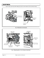
10. Check the starting solenoid operation. Turn the key
switch to the ‘OFF’ position.
a) Place the DVOM (set to appropriate DC
volts scale) positive (+) probe on the ter-
minal with the black/white (BLK/WHT)
wire solenoid. Place negative (-) probe on
to ground.
b) The DVOM should indicate reference
battery voltage (approximately 12 V).
c) Turn the key switch to the ‘OFF’ position.
The DVOM should indicate 0 V.
d) Replace solenoid if 12 V is not indicated
with the switch turned to ‘ON’.
BATTERY VOLTAGE TEST
Hydrogen gas formed
during battery charging
i s e x p l o s i v e a n d c a n
cause severe personal injury or death. Avoid any
electrical spark or open flame near battery.
Do not overcharge battery.
If the temperature of the battery or the
ambient temperature is below 60° F (15° C),
the capacity of the battery will be less. It will require more time
to charge.
A cold battery will build up voltage and more rapidly reduce the
charging rate.
Batteries that are new or have been stored must be fully
charged before being tested or placed in vehicle.
!
!
!
!
Содержание ST 4X4
Страница 6: ...Page iv Repair and Service Manual TABLE OF CONTENTS Notes...
Страница 10: ...Repair and Service Manual SAFETY INFORMATION Page viii Notes...
Страница 12: ...GENERAL INFORMATION ROUTINE MAINTENANCE Page A ii Repair and Service Manual Notes...
Страница 24: ...SAFETY Page B ii Repair and Service Manual Notes...
Страница 34: ...BODY AND TRUCKBED Page C ii Repair and Service Manual Notes...
Страница 50: ...BRAKES Page D ii Repair and Service Manual Notes...
Страница 68: ...CONTINUOUSLY VARIABLE TRANSMISSION CVT Page E ii Repair and Service Manual Notes...
Страница 74: ...DIRECTION AND DRIVE SELECTOR Page F ii Repair and Service Manual Notes...
Страница 80: ...ELECTRICAL Page G ii Repair and Service Manual Notes...
Страница 114: ...FRONT SUSPENSION AND STEERING Page J ii Repair and Service Manual Notes...
Страница 128: ...FUEL SYSTEM Page K ii Repair and Service Manual Notes...
Страница 136: ...PAINT Page L ii Repair and Service Manual Notes...
Страница 142: ...REAR AXLE AND SUSPENSION Page M ii Repair and Service Manual Notes...
Страница 152: ...SPEED CONTROL Page N ii Repair and Service Manual Notes...
Страница 160: ...TROUBLESHOOTING Page P ii Repair and Service Manual Notes...
Страница 168: ...WHEELS AND TIRES Page R ii Repair and Service Manual Notes...
Страница 174: ...GENERAL SPECIFICATIONS Page S ii Repair and Service Manual Notes...
Страница 180: ...LIMITED WARRANTY Page T ii Repair and Service Manual Notes...
Страница 182: ...Page T 2 Repair and Service Manual LIMITED WARRANTY Notes...

