


BODY AND TRUCKBED
Page C-4
4GRCKTCPF5GTXKEG/CPWCN
4GCFCNNQH5GEVKQP$CPFVJKUUGEVKQPDGHQTGCVVGORVKPICP[RTQEGFWTG2C[RCTVKEWNCTCVVGPVKQPVQCNN0QVGU%CWVKQPUCPF9CTPKPIU
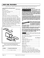
Tighten the hardware per torque specification table given
below.
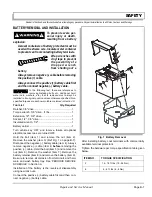
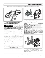
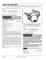
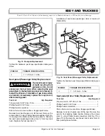
Rear Hitch Receiver Replacement
6JGTGCTJKVEJKUJGCX[
6QRTGXGPVRQUUKDNGRGT
UQPCNKPLWT[KVKUUVTQPIN[
TGEQOOGPFGFVJCVCPCUUKUVCPV
DGWUGFYJGPTGOQX
KPIQTKPUVCNNKPIVJGTGCTTGEGKXGT
Tool List
Qty. Required
Ratchet, 1/2" drive ....................................................... 1
Torque wrench, 1/2" drive, ft. lbs................................. 1
Socket, 3/4", 1/2" drive ................................................ 1
Impact socket, 9/16", 1/2" drive................................... 1
Wrench, 3/4"................................................................ 1
Floor jack, 1 1/2 ton..................................................... 1
Jack stands ................................................................. 2
Wheel chocks .............................................................. 4
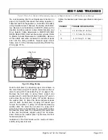
Remove any hitch installed in the receiver. It is neces-
sary to remove the driver side wheel in order to maneu-
ver the receiver above the driver side spring before tilting
down and removing below the spring on the passenger
side. Loosen the four nuts on the rear driver side wheel
half turn.
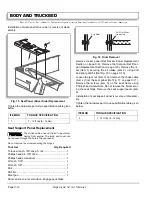
Lift and support rear of the vehicle per SAFETY section.
Remove the four rear driver side wheel nuts and remove
the wheel. With adequate help, support the rear hitch.
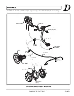
Hold the bolt (item 1) using 3/4" socket, and remove the
nuts (item 2) using 3/4" wrench (Ref Fig. 7 on page C-4).
Remove washers (item 3). Remove the bolts (item 1) and
the backing plates (item 4). Lower the receiver (item 5)
and move through the driver side above the spring.
Lower the passenger side below the spring and pull from
vehicle.
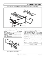
Installation of rear hitch is the reverse of disassembly
using new lock nuts.
Tighten the hardware per torque specification table given
below.
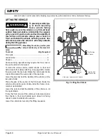
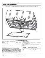
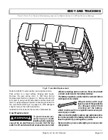
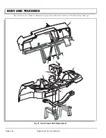
Truck Bed Replacement
6JGVTWEMDGFKUJGCX[
CPFCYMYCTFVQJCPFNG
6QRTGXGPVRQUUKDNGRGT
UQPCNKPLWT[KVKUUVTQPIN[TGEQOOGPFGFVJCVCP
CUUKUVCPVQTCFGSWCVGNKHVKPIFGXKEGDGWUGFYJGP
TGOQXKPIQTKPUVCNNKPIVJGVTWEMDGFHTQOXGJKENG
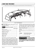
6QTGFWEGVJGRQUUKDKNKV[QHRGTUQPCNKPLWT[QTFGCVJ
TGUWNVKPIHTQOKPEQTTGEVNQCFKPIQHXGJKENGOCMGUWTG
EQTTGEVUCHGV[NCDGNKUKPUVCNNGFCPFOCKPVCKPGFKP
IQQFEQPFKVKQP
6QRTGXGPVRGTUQPCNKPLWT[TGUWNVKPIHTQOCHCNNKPI
VTWEMDGFJCXGCPCUUKUVCPVVQJQNFVTWEMDGFKP
TCKUGFRQUKVKQPYJKNGTGRNCEKPIICUURTKPI
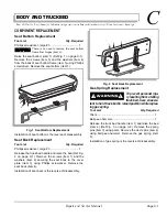
If the truck bed is to be replaced, the label plate
must be removed and reinstalled on the new
truck bed properly.
Tool List
Qty. Required
Needle nose pliers .......................................................1
Ball peen hammer .......................................................1
ITEM NO
TORQUE SPECIFICATION
2
8 - 10 ft. lbs (11 - 13 Nm)
!
!
Fig. 7 Rear Hitch Receiver Replacement
ITEM NO
TORQUE SPECIFICATION
2
55 - 60 ft. lbs (75 - 81 Nm)
3
1
5
4
2
!
!
Содержание ST 4X4
Страница 6: ...Page iv Repair and Service Manual TABLE OF CONTENTS Notes...
Страница 10: ...Repair and Service Manual SAFETY INFORMATION Page viii Notes...
Страница 12: ...GENERAL INFORMATION ROUTINE MAINTENANCE Page A ii Repair and Service Manual Notes...
Страница 24: ...SAFETY Page B ii Repair and Service Manual Notes...
Страница 34: ...BODY AND TRUCKBED Page C ii Repair and Service Manual Notes...
Страница 50: ...BRAKES Page D ii Repair and Service Manual Notes...
Страница 68: ...CONTINUOUSLY VARIABLE TRANSMISSION CVT Page E ii Repair and Service Manual Notes...
Страница 74: ...DIRECTION AND DRIVE SELECTOR Page F ii Repair and Service Manual Notes...
Страница 80: ...ELECTRICAL Page G ii Repair and Service Manual Notes...
Страница 114: ...FRONT SUSPENSION AND STEERING Page J ii Repair and Service Manual Notes...
Страница 128: ...FUEL SYSTEM Page K ii Repair and Service Manual Notes...
Страница 136: ...PAINT Page L ii Repair and Service Manual Notes...
Страница 142: ...REAR AXLE AND SUSPENSION Page M ii Repair and Service Manual Notes...
Страница 152: ...SPEED CONTROL Page N ii Repair and Service Manual Notes...
Страница 160: ...TROUBLESHOOTING Page P ii Repair and Service Manual Notes...
Страница 168: ...WHEELS AND TIRES Page R ii Repair and Service Manual Notes...
Страница 174: ...GENERAL SPECIFICATIONS Page S ii Repair and Service Manual Notes...
Страница 180: ...LIMITED WARRANTY Page T ii Repair and Service Manual Notes...
Страница 182: ...Page T 2 Repair and Service Manual LIMITED WARRANTY Notes...


