FRONT SUSPENSION AND STEERING
Page J-2
Repair and Service Manual
Read all of Section B and this section before attempting any procedure. Pay particular attention to all Notes, Cautions and Warnings
FRONT SUSPENSION
In the following text, there are references to
removing/installing bolts, etc. Additional hard-
ware (nuts, washers, etc.) that is removed must always be
installed in its original positions unless otherwise specified.
Non-specified torque specifications are shown in the table con-
tained in Section A.
To reduce the possibility
of personal injury, place
wheel chocks in front
and behind the rear wheels. Check the stability of the
vehicle on the jack stands before starting any repair
procedure. Never work on a vehicle that is supported
by a jack alone.
To prevent injury caused by a broken socket, use only
sockets designed for impact wrench use. Never use a
conventional socket.
Front Suspension Disassembly
Tool List
Qty. Required
Torque wrench, 1/2" drive, 165 ft. lbs capacity ............ 1
Impact wrench, 1/2" drive ............................................ 1
Extension, 6", 1/2" drive ............................................. 1
Socket, 3/4", 1/2" drive ................................................ 1
Socket, 1 1/8", 1/2" drive ............................................. 1
Impact socket, 3/4", 1/2" drive ..................................... 1
Allen wrench, 9mm, 1/2" drive .................................... 1
Wrench, 3/4"................................................................ 1
Wrench, 9/16".............................................................. 1
Wrench, 11/16" ............................................................ 1
Plastic faced hammer.................................................. 1
Straight blade screwdriver ........................................... 1
Needle nose pliers....................................................... 1
Floor jack, 1 1/2 ton..................................................... 1
Jack stands ................................................................. 2
Wheel chocks .............................................................. 4
Wheels and Brake Removal
Loosen the four nuts on the front wheels half turn.
Lift and support front of the vehicle per SAFETY section.
Remove the four front wheel nuts and remove the wheel.
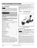
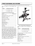
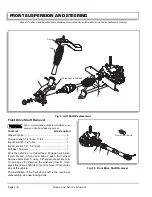
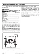
Remove the bolt (item 1) using Allen wrench and exten-
sion (Ref Fig. 2 on page J-2). Remove the washer (item
2). Remove front brake caliper (item 3) and secure to the
frame using wire ties. Remove the rotor (item 4).
The installation of the wheels and brake is the reverse of
disassembly (Refer WHEELS AND TIRES section for
wheel lug nuts torque specification).
Tighten the hardware per torque specification table
below.
Tie Rod End Removal
Never use a ball joint separator (Pickle
fork), it will damage the joint.
After replacing the tie rod end, the tie rod is
likely to be out of adjustment. The vehicle will
require a wheel alignment before being returned to service (Ref
Wheel Alignment Section on page J-12).
Jam Nut is LH threaded on passenger side and RH threaded on
driver side.
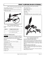
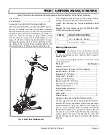
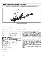
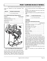
Remove the spindle cap (item 1) using a straight blade
screwdriver and plastic faced hammer (Ref Fig. 3 on
page J-3). Remove the lock nut (item 2) using a 1 1/8"
socket. Remove the outer brake washer (item 3).
Remove the cotter pin (item 4) and castle nut (item 5)
using needle nose pliers and 3/4" wrench. Remove the
washer (item 6) from tie rod end. Strike knuckle (item 7)
with plastic faced hammer to separate tie rod end. Hold
tie rod on flat groove using 9/16" wrench and loosen jam
nut (item 8) using 11/16" wrench. Remove the tie rod
end.
!
!
ITEM NO
TORQUE SPECIFICATION
1
42 - 47 ft.lbs (57 - 64 Nm)
Fig. 2 Brake Removal
4
3
2
1
Brake Line
Содержание ST 4X4
Страница 6: ...Page iv Repair and Service Manual TABLE OF CONTENTS Notes...
Страница 10: ...Repair and Service Manual SAFETY INFORMATION Page viii Notes...
Страница 12: ...GENERAL INFORMATION ROUTINE MAINTENANCE Page A ii Repair and Service Manual Notes...
Страница 24: ...SAFETY Page B ii Repair and Service Manual Notes...
Страница 34: ...BODY AND TRUCKBED Page C ii Repair and Service Manual Notes...
Страница 50: ...BRAKES Page D ii Repair and Service Manual Notes...
Страница 68: ...CONTINUOUSLY VARIABLE TRANSMISSION CVT Page E ii Repair and Service Manual Notes...
Страница 74: ...DIRECTION AND DRIVE SELECTOR Page F ii Repair and Service Manual Notes...
Страница 80: ...ELECTRICAL Page G ii Repair and Service Manual Notes...
Страница 114: ...FRONT SUSPENSION AND STEERING Page J ii Repair and Service Manual Notes...
Страница 128: ...FUEL SYSTEM Page K ii Repair and Service Manual Notes...
Страница 136: ...PAINT Page L ii Repair and Service Manual Notes...
Страница 142: ...REAR AXLE AND SUSPENSION Page M ii Repair and Service Manual Notes...
Страница 152: ...SPEED CONTROL Page N ii Repair and Service Manual Notes...
Страница 160: ...TROUBLESHOOTING Page P ii Repair and Service Manual Notes...
Страница 168: ...WHEELS AND TIRES Page R ii Repair and Service Manual Notes...
Страница 174: ...GENERAL SPECIFICATIONS Page S ii Repair and Service Manual Notes...
Страница 180: ...LIMITED WARRANTY Page T ii Repair and Service Manual Notes...
Страница 182: ...Page T 2 Repair and Service Manual LIMITED WARRANTY Notes...

