BRAKES
Page D-2
Repair and Service Manual
Read all of Section B and this section before attempting any procedure. Pay particular attention to all Notes, Cautions and Warnings
GENERAL
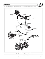
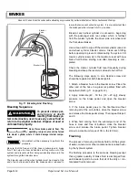
How The Hydraulic System Works
A hydraulic system actuates the brakes through two sep-
arate circuits. The rear master cylinder reservoir oper-
ates the front disc brakes, and the front operates the rear
drum brakes. The system transmits the power required to
activate the friction surfaces (pads front and brake shoes
rear) of the braking system from the pedal to the individ-
ual brake units at each wheel.
Hydraulic system operation:
When at rest, the entire system is full of brake fluid. Upon
application of the brake pedal, fluid trapped in front of the
master cylinder piston is forced through the brake lines to
the wheel cylinders. Here, it forces pistons outwards
against the brake pads or shoes.
a) The front brake pad contacts the brake disc and
continued movement of the piston moves the
brake caliper that contains the second brake pad.
The two brake pads apply a clamping force to the
disc.
Upon release of the brake pedal, a spring located
inside the master cylinder immediately returns the
piston to the normal position. The front brake pis-
ton retracts slightly as the piston seal retracts. The
piston returns the brake fluid to its original position
within the rear reservoir of the master cylinder,
and the attached brake pads retract from the disc.
b) Upon release of the brake pedal, a spring located
inside the master cylinder immediately returns the
piston to the normal position. The rear brake shoe
return springs retract the brake shoes and wheel
cylinders which returns the brake fluid to its origi-
nal position within the front reservoir of the master
cylinder.
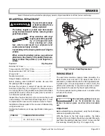
Rear Wheel Brake
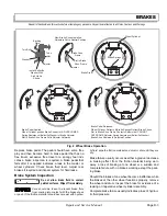
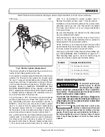
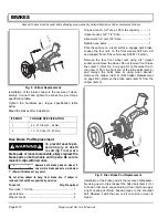
The 160 x 30mm hydraulic brake is a leading-trailing
design. The shoes are held to the backing plate by hold-
down springs, pins, and spring retainers. The shoes are
fitted to the anchor at the bottom and secured by a lower
shoe to shoe spring. At the top, the shoe web rests on
the wheel cylinder piston.
The shoes are held to the wheel cylinder pistons by the
upper shoe to shoe spring. The wheel cylinders are a
double piston design, providing even distribution of force
to each shoe. There are no links. Shoes rest directly on
the piston ends. Wheel cylinders incorporate external
boots.
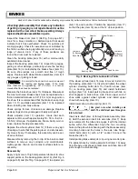
Brake adjustment is automatic (Ref Fig. 2 on page D-3).
Adjustment takes place, if needed, whenever the brakes
are applied (forward or reverse stop or when the vehicle
is stationary). Upon any brake application, the shoes
move outward contacting the drum. As the shoes move
outward, the automatic adjuster levers (attached to each
shoe by a pin) follow the shoe movement. The automatic
adjuster pin is smaller than the slot in the brake shoe
web; therefore, when the brakes are released, the shoes
are allowed to return slightly, providing brake shoe to
drum running clearance.
The rear brake includes a parking feature consisting of a
lever and strut. The lever is applied by a cable attached
to the parking brake lever (hand operated). The parking
brake is used to retain the vehicle when stationary.
Front Disc Brake
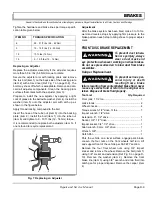
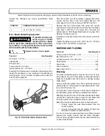
The disc brake assembly is a single cylinder, one piece
housing. The cylinder contains a piston and a piston seal
containing a return spring. There are two brake pads, on
either side of the disc. The brake pad mounted to the pis-
ton will move out and in of the cylinder when the brakes
are operated and released. Hydraulic pressure from the
brake master cylinder enters the brake cylinder and
forces the piston and pad against the rotating disc. As
brake pressure continues the piston mounted pad ‘pulls’
the caliper with the second brake pad against the oppo-
site side of the rotating disc. This creates friction to stop
the vehicle.The caliper is held in relative position to the
mounting bracket with sliding pins secured to the caliper.
Maintenance of the single disc brake may include lubri-
cation of slide pins, bleeding, performing operational
checks, and the checking pad and disc wear.
MAINTENANCE
Daily Brake Performance Test
To assure correct braking performance, all peri-
odic maintenance, inspections and procedures
must be performed as indicated in the Periodic Service Sched-
ule in Section A of this manual. It is important that a Daily
Brake Performance Test be performed and the entire brake
system be serviced in accordance with the Periodic Ser-
vice Schedule.
The brake system must be bled whenever any part of the
brake system has been replaced.
Содержание ST 4X4
Страница 6: ...Page iv Repair and Service Manual TABLE OF CONTENTS Notes...
Страница 10: ...Repair and Service Manual SAFETY INFORMATION Page viii Notes...
Страница 12: ...GENERAL INFORMATION ROUTINE MAINTENANCE Page A ii Repair and Service Manual Notes...
Страница 24: ...SAFETY Page B ii Repair and Service Manual Notes...
Страница 34: ...BODY AND TRUCKBED Page C ii Repair and Service Manual Notes...
Страница 50: ...BRAKES Page D ii Repair and Service Manual Notes...
Страница 68: ...CONTINUOUSLY VARIABLE TRANSMISSION CVT Page E ii Repair and Service Manual Notes...
Страница 74: ...DIRECTION AND DRIVE SELECTOR Page F ii Repair and Service Manual Notes...
Страница 80: ...ELECTRICAL Page G ii Repair and Service Manual Notes...
Страница 114: ...FRONT SUSPENSION AND STEERING Page J ii Repair and Service Manual Notes...
Страница 128: ...FUEL SYSTEM Page K ii Repair and Service Manual Notes...
Страница 136: ...PAINT Page L ii Repair and Service Manual Notes...
Страница 142: ...REAR AXLE AND SUSPENSION Page M ii Repair and Service Manual Notes...
Страница 152: ...SPEED CONTROL Page N ii Repair and Service Manual Notes...
Страница 160: ...TROUBLESHOOTING Page P ii Repair and Service Manual Notes...
Страница 168: ...WHEELS AND TIRES Page R ii Repair and Service Manual Notes...
Страница 174: ...GENERAL SPECIFICATIONS Page S ii Repair and Service Manual Notes...
Страница 180: ...LIMITED WARRANTY Page T ii Repair and Service Manual Notes...
Страница 182: ...Page T 2 Repair and Service Manual LIMITED WARRANTY Notes...

