BRAKES
Page D-12
Repair and Service Manual
Read all of Section B and this section before attempting any procedure. Pay particular attention to all Notes, Cautions and Warnings
Bleeding Sequence
To prevent serious per-
sonal injury or death
resulting from brake sys-
tem contamination, never reuse any excess fluid or
return to the original container. Dispose of used or
old brake fluid properly.
Do not force brake pedal to floor. The
operating rod jam nut could be forced
into master cylinder where it could damage internal compo-
nents.
An assistant will be necessary to perform this
procedure.
Be sure that the free end of the hose is submerged in brake
fluid. This helps to show air bubbles as they come out of the
system, and prevents air from being accidentally drawn into the
system through the bleeder screw.
The bleeder valve at the wheel cylinder must be closed at the
end of each stroke and before the brake pedal is released to
insure that air cannot enter the system. It is also important that
the brake pedal be returned to full ‘up’ position.
Bleed at each wheel cylinder in succession, beginning
with the passenger side rear wheel, which is farthest
from the master cylinder, the driver side rear wheel and
the front wheel brakes.
Use a clean cloth to wipe off the master cylinder reservoir
and wheel cylinder bleeder valves. Clean each fitting
before opening to prevent contaminating the system. Fill
master cylinder reservoir to the maximum level with new
brake fluid before starting and after bleeding is com-
pleted.
Check the master cylinder fluid level frequently during
bleeding and keep the reservoirs at least one-half full.
The following steps apply to one bleeder screw and
should be repeated at both bleeder points.
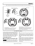
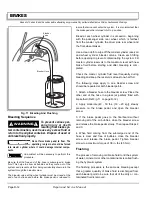
1. Attach a bleeder hose to the bleeder screw. Place the
other end of the hose in a glass jar partially filled with
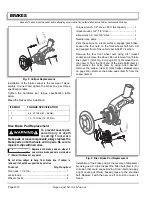
brake fluid (Ref Fig. 11 on page D-12).
2. Apply moderate (40 - 50 lbs. [18 – 20 kg]), steady
pressure on the brake pedal, and open the bleeder
screw.
3. If the brake pedal goes to the floorboard without
removing all of the air bubbles, close the bleeder screw
and release the brake pedal slowly. Then repeat Steps 2
and 3.
4. When fluid coming from the submerged end of the
hose is clear and free of bubbles, close the bleeder
screw and release the brake pedal. Tighten bleeder
screw to a maximum torque of 38 in. lbs (4.3 Nm).
Flushing
The process of removing old brake fluid to rid the system
of water, mineral oil or other contaminants is called flush-
ing the hydraulic system.
The flushing procedure is the same as bleeding except
that a greater quantity of brake fluid is discharged from
each bleeder point to be sure that all of the dirty or con-
taminated fluid is removed.
Fig. 11 Bleeding And Flushing
Bleeder Hose
Bleeder
Valve
!
!
Содержание ST 4X4
Страница 6: ...Page iv Repair and Service Manual TABLE OF CONTENTS Notes...
Страница 10: ...Repair and Service Manual SAFETY INFORMATION Page viii Notes...
Страница 12: ...GENERAL INFORMATION ROUTINE MAINTENANCE Page A ii Repair and Service Manual Notes...
Страница 24: ...SAFETY Page B ii Repair and Service Manual Notes...
Страница 34: ...BODY AND TRUCKBED Page C ii Repair and Service Manual Notes...
Страница 50: ...BRAKES Page D ii Repair and Service Manual Notes...
Страница 68: ...CONTINUOUSLY VARIABLE TRANSMISSION CVT Page E ii Repair and Service Manual Notes...
Страница 74: ...DIRECTION AND DRIVE SELECTOR Page F ii Repair and Service Manual Notes...
Страница 80: ...ELECTRICAL Page G ii Repair and Service Manual Notes...
Страница 114: ...FRONT SUSPENSION AND STEERING Page J ii Repair and Service Manual Notes...
Страница 128: ...FUEL SYSTEM Page K ii Repair and Service Manual Notes...
Страница 136: ...PAINT Page L ii Repair and Service Manual Notes...
Страница 142: ...REAR AXLE AND SUSPENSION Page M ii Repair and Service Manual Notes...
Страница 152: ...SPEED CONTROL Page N ii Repair and Service Manual Notes...
Страница 160: ...TROUBLESHOOTING Page P ii Repair and Service Manual Notes...
Страница 168: ...WHEELS AND TIRES Page R ii Repair and Service Manual Notes...
Страница 174: ...GENERAL SPECIFICATIONS Page S ii Repair and Service Manual Notes...
Страница 180: ...LIMITED WARRANTY Page T ii Repair and Service Manual Notes...
Страница 182: ...Page T 2 Repair and Service Manual LIMITED WARRANTY Notes...

