FRONT SUSPENSION AND STEERING
Page J-12
Repair and Service Manual
Read all of Section B and this section before attempting any procedure. Pay particular attention to all Notes, Cautions and Warnings
MAINTENANCE
Wheel Alignment
Attempting to turn the tie-rod with wire
tie on the boot, will damage it.
Tool List
Qty. Required
Wrench, 9/16".............................................................. 1
Wrench, 11/16" ............................................................ 1
Needle nose pliers....................................................... 1
Tape measure.............................................................. 1
Chalk ....................................................................... A/R
Diagonal cutter ............................................................ 1
Floor jack, 1 1/2 ton..................................................... 1
Jack stands ................................................................. 2
Wheel chocks .............................................................. 4
Lift and support front of vehicle per SAFETY section.
Rotate each wheel and scribe or chalk a line around the
circumference of the tire at the center of the thread pat-
tern. Lower the vehicle and roll it forward approximately 5
ft. in order to allow the tires to take their normal running
position.
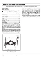
Measure the distance between the chalk lines at both the
front and rear of the tires. The measurement taken at the
front of the tire should be between 0"- 1/4" (0mm-6mm)
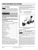
more than the rear (TOE OUT) (Ref Fig. 15 on page J-
12).
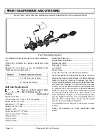
To adjust the wheel alignment, cut-off wire tie on boot at
steering unit using diagonal cutters. Pull boot away from
housing and hold tie rod on flat groove using 9/16"
wrench
.
Loosen jam nut using 11/16" wrench. Turn the
tie rod so that the wheel moves in or out as desired. Posi-
tion boot over housing. Use a new wire tie to fasten the
boot being sure that the wire tie is located over the
groove in the housing.
Test drive the vehicle and confirm that the steering wheel
is correctly centered. If not, remove steering wheel and
rotate it to correct position.
Fig. 15 Wheel Alignment
VIEW FROM UNDERSIDE OF VEHICLE
0" — 1/4" more than rear
Rear
Front of Vehicle
Содержание ST 4X4
Страница 6: ...Page iv Repair and Service Manual TABLE OF CONTENTS Notes...
Страница 10: ...Repair and Service Manual SAFETY INFORMATION Page viii Notes...
Страница 12: ...GENERAL INFORMATION ROUTINE MAINTENANCE Page A ii Repair and Service Manual Notes...
Страница 24: ...SAFETY Page B ii Repair and Service Manual Notes...
Страница 34: ...BODY AND TRUCKBED Page C ii Repair and Service Manual Notes...
Страница 50: ...BRAKES Page D ii Repair and Service Manual Notes...
Страница 68: ...CONTINUOUSLY VARIABLE TRANSMISSION CVT Page E ii Repair and Service Manual Notes...
Страница 74: ...DIRECTION AND DRIVE SELECTOR Page F ii Repair and Service Manual Notes...
Страница 80: ...ELECTRICAL Page G ii Repair and Service Manual Notes...
Страница 114: ...FRONT SUSPENSION AND STEERING Page J ii Repair and Service Manual Notes...
Страница 128: ...FUEL SYSTEM Page K ii Repair and Service Manual Notes...
Страница 136: ...PAINT Page L ii Repair and Service Manual Notes...
Страница 142: ...REAR AXLE AND SUSPENSION Page M ii Repair and Service Manual Notes...
Страница 152: ...SPEED CONTROL Page N ii Repair and Service Manual Notes...
Страница 160: ...TROUBLESHOOTING Page P ii Repair and Service Manual Notes...
Страница 168: ...WHEELS AND TIRES Page R ii Repair and Service Manual Notes...
Страница 174: ...GENERAL SPECIFICATIONS Page S ii Repair and Service Manual Notes...
Страница 180: ...LIMITED WARRANTY Page T ii Repair and Service Manual Notes...
Страница 182: ...Page T 2 Repair and Service Manual LIMITED WARRANTY Notes...

