REAR AXLE AND SUSPENSION
Page M-4
Repair and Service Manual
Read all of Section B and this section before attempting any procedure. Pay particular attention to all Notes, Cautions and Warnings
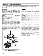
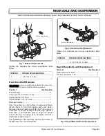
Hold the nut (item 1) using open end wrench and remove
the screw (item 2) using torx bit screwdriver (Ref Fig. 5
on page M-3). Remove the rear differential guard (item
3).
The installation of the rear differential guard is the
reverse of disassembly using new lock nuts.
Tighten the hardware per torque specification table
below.
Rear Axle Replacement
To reduce the possibility
of severe personal injury
or death, follow the lift-
ing procedure in Section B of this manual. Place
wheel chocks in front and behind each wheel not
being raised and check the stability of the vehicle on
the jack stands before starting any repair procedure.
Never work on a vehicle that is supported by a jack
alone.
To reduce possibility of personal injury while remov-
ing rear axle, be sure to support differential when
removing the ‘U’ bolts.
Dispose of used brake fluid properly. Never reuse old
fluid.
Allow brake fluid to drain into pan for
disposal. Whenever hydraulic brake
line is removed, bleed the brake at the end of installation.
Tool List
Qty. Required
Floor jack, 1 1/2 ton..................................................... 1
Jack stands ................................................................. 2
Wheel chocks .............................................................. 4
Ratchet, 3/8" drive ....................................................... 1
Torque wrench, 3/8" drive, ft. lbs ................................. 1
Impact wrench, 1/2" drive ............................................ 1
Socket, 1/2", 3/8" drive ................................................ 1
Deep well socket, 9/16", 1/2" drive.............................. 1
Impact socket, 1/2", 1/2" drive ..................................... 1
Allen wrench, 1/8" ....................................................... 1
Wrench, 9/16".............................................................. 1
Wrench, 3/4"................................................................ 1
Box end wrench, 3/8" .................................................. 1
Ball peen hammer .......................................................1
Straight blade screw driver ..........................................1
Pliers............................................................................ 1
Needle nose pliers .......................................................1
Drain Pan..................................................................... 1
Thread locking sealant ............................................. AR
Anti-seize compound ................................................ AR
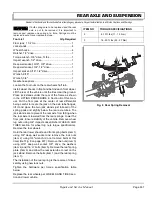
Loosen the four nuts on the rear wheels half turn.
Lift and support the vehicle per SAFETY section.
Remove the four rear wheel nuts and remove the wheel.
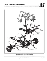
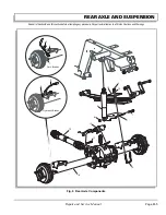
Release truck bed handle and lift the bed. Remove the
cotter pins (item 1), clevis pins (item 2) and retaining
rings (E - rings) (item 3) from the sub frame brackets
using needle nose pliers (Ref Fig. 6 on page M-5). Dis-
connect the park brake cables.
Remove banjo bolts (item 4) and copper gaskets (item
5). Disconnect hydraulic brake lines (item 6) at backing
plates. Remove brake lines (item 6).
Hold the bolt (item 7) using 9/16" wrench and remove
lock nut (item 8) using 9/16" socket (Ref Fig. 6 on page
M-5). Remove bottom end of the shock absorber (item
9). Remove the solenoid (item 10) (Ref Solenoid
Replacement Section on page M-2). Remove the locking
bolt (item 11) on the rear drive shaft (item 12) using 1/2"
impact socket.
Place floor jack under center section of rear axle and
raise it just enough to take weight off spring. Support
both rear axle and frame properly. Remove lock nuts
(item 13) using 9/16" deep well socket, remove washers
(item 14) and ‘U’ bolts (item 15). Remove leaf spring
plate (item 16) and shock mounting bracket (item 17).
Lower the rear axle (item 18) and pull it out from under
side of the vehicle.
The installation of the rear axle is the reverse of disas-
sembly using new locking bolts and new lock nuts.
Apply anti-seize compound to all splines.
Replace the rear wheels per WHEELS AND TIRES sec-
tion and lower vehicle.
Bleed brake system before installing load bed. See
HYDRAULIC BRAKES section.
ITEM NO
TORQUE SPECIFICATIONS
2
18 - 22 ft. lbs (24 - 30 Nm)
!
!
Содержание ST 4X4
Страница 6: ...Page iv Repair and Service Manual TABLE OF CONTENTS Notes...
Страница 10: ...Repair and Service Manual SAFETY INFORMATION Page viii Notes...
Страница 12: ...GENERAL INFORMATION ROUTINE MAINTENANCE Page A ii Repair and Service Manual Notes...
Страница 24: ...SAFETY Page B ii Repair and Service Manual Notes...
Страница 34: ...BODY AND TRUCKBED Page C ii Repair and Service Manual Notes...
Страница 50: ...BRAKES Page D ii Repair and Service Manual Notes...
Страница 68: ...CONTINUOUSLY VARIABLE TRANSMISSION CVT Page E ii Repair and Service Manual Notes...
Страница 74: ...DIRECTION AND DRIVE SELECTOR Page F ii Repair and Service Manual Notes...
Страница 80: ...ELECTRICAL Page G ii Repair and Service Manual Notes...
Страница 114: ...FRONT SUSPENSION AND STEERING Page J ii Repair and Service Manual Notes...
Страница 128: ...FUEL SYSTEM Page K ii Repair and Service Manual Notes...
Страница 136: ...PAINT Page L ii Repair and Service Manual Notes...
Страница 142: ...REAR AXLE AND SUSPENSION Page M ii Repair and Service Manual Notes...
Страница 152: ...SPEED CONTROL Page N ii Repair and Service Manual Notes...
Страница 160: ...TROUBLESHOOTING Page P ii Repair and Service Manual Notes...
Страница 168: ...WHEELS AND TIRES Page R ii Repair and Service Manual Notes...
Страница 174: ...GENERAL SPECIFICATIONS Page S ii Repair and Service Manual Notes...
Страница 180: ...LIMITED WARRANTY Page T ii Repair and Service Manual Notes...
Страница 182: ...Page T 2 Repair and Service Manual LIMITED WARRANTY Notes...


